24 Rockwell Automation Publication 7000L-UM301F-EN-P - March 2020
Chapter 1 Overview of Drive
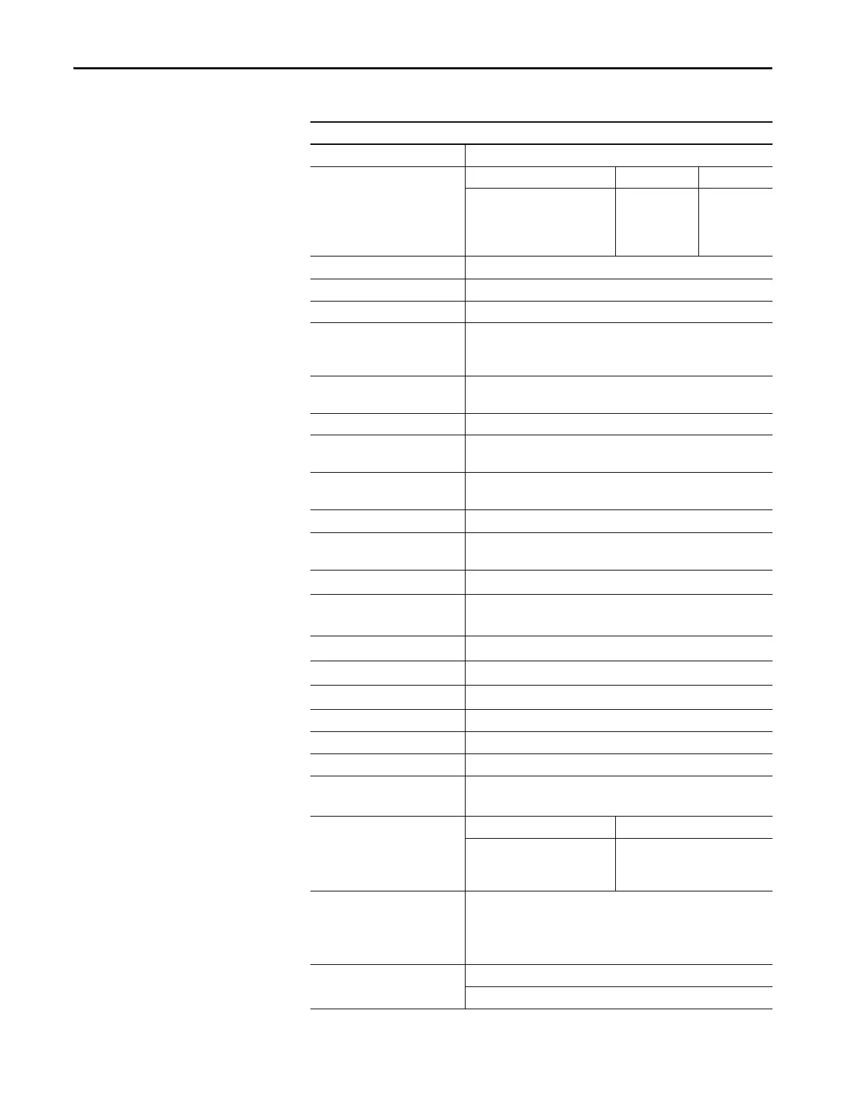
Rectifier Switch Cooling Double Sided, Low Thermal Stress
Number of Rectifier Devices per phase Voltage AFE 18 Pulse
2400V
3300V
4160V
6600V
2
4
4
6
6
6
6
6
Output Current THD (1
st
…49
th
)< 5%
Output Waveform to Motor Sinusoidal Current / Voltage
Medium Voltage Isolation Fiber Optic
Modulation techniques Selective Harmonic Elimination (SHE)
Synchronous Trapezoidal PWM
Asynchronous or Synchronous SVM (Space Vector Modulation)
Control Method Digital Sensorless Direct Vector
Full Vector Control with Encoder Feedback (Optional)
Tuning Method Auto Tuning via Setup Wizard
Speed Regulator Bandwidth 1...10 rad/s with standard control
1...20 rad/s with HPTC (optional)
Torque Regulator Bandwidth 15...50 rad/s with standard control
80...100 rad/s with HPTC (optional)
Torque Accuracy with HPTC (optional) +/- 5%
Speed Regulation
0.1% without Encoder Feedback
0.01...0.02% with Encoder Feedback
Acceleration/Deceleration Range
Independent Accel/Decel – 4 x 30 s
Acceleration/Deceleration Ramp
Rates
4 x Independent Accel/Decel
S Ramp Rate
Independent Accel/Decel – 2 x 999 s
Critical Speed Avoidance
3 x Independent with Adjustable bandwidth
Stall Protection
Adjustable time delay
Load Loss Detection Adjustable level, delay, speed set points
Control Mode Speed or Torque
Current Limit Adjustable in Motoring and Regenerative
Output Frequency Range 0.2...75 Hz (Standard)
75 Hz...85Hz (Optional - need specific Motor Filter Capacitor [MFC])
Service Duty Rating Normal Duty Heavy Duty
110% Overload for 1 min. every 10
min.
(Variable Torque Load)
150% Overload for 1 min. every 10
min.
(Constant Torque Load)
Typical VFD Efficiency > 97.5% (AFE)
> 98% (18 Pulse)
Contact Factory for Guaranteed Efficiency
of Specific Drive Rating
Input Power Factor AFE Rectifier
0.95 minimum, 10...100% Load
Table 1 - General Design Specifications (Continued)
Description

 Loading...


