Rockwell Automation Publication 7000L-UM301F-EN-P - March 2020 315
Component Definition and Maintenance Chapter 5
16. Apply a 60Hz, 33% duty cycle signal to the OP1 fiber optic input.
17. Verify that the diagnostics transmitter LED, OT1, is on.
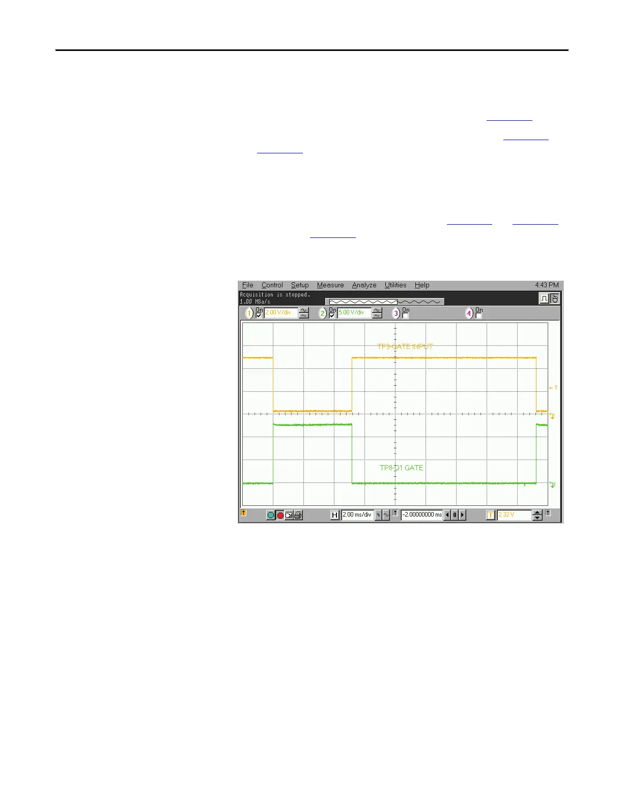
18. Verify that the signals at TP9 and TP8 are as shown in Figure 261
.
19. Verify that the signal between TP1 and TP2 is as shown in Figure 262
and
Figure 263
.
20. Remove the jumper between TB3-1 and TB3-2.
21. Apply a constant fiber optic signal to the OP1 input.
22. Apply a 60 Hz, 33% duty cycle signal, at a 0 to +2V level, between the
TB1-2 input and COM. Verify the signals in Figure 264
and Figure 265.
Note that in Figure 265
there should be a 220 µS, ±20 µS time between the
rising edge of the U4-pin7 pulse and the falling edge of the TP7 signal.
Figure 261 - Gating pulses
 Loading...


