EasyManuals Logo

Rockwell Automation Allen-Bradley PowerFlex 7000 User Manual

Rockwell Automation Allen-Bradley PowerFlex 7000
434 pages
To Next Page IconTo Next Page
To Previous Page IconTo Previous Page
Page #48 background imageLoading...
Page #48 background image
48 Rockwell Automation Publication 7000L-UM301F-EN-P - March 2020
Chapter 2 Drive Installation
3. Route the control wiring which has been coiled up and left hanging in the
upper area of the motor filter capacitor section, back up through the two
grommeted cutouts back into the wireway. There is a fiber optic cable in
this bundle and care must be taken not to damage it. The fiber optic cable,
control power wires and the “XIO link” cable will be required in the pump
control cabinet.
Figure 31 - Control Wiring
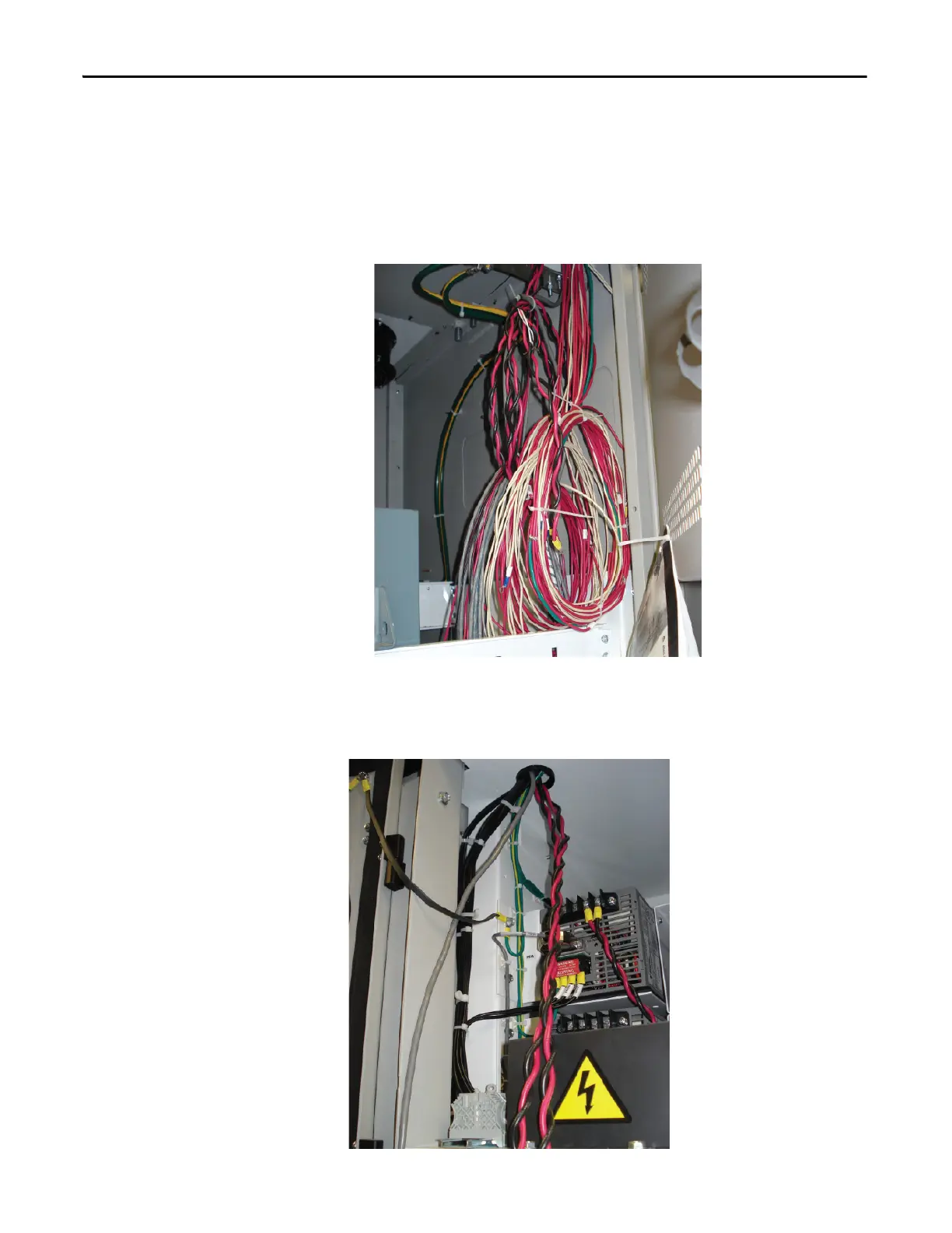
4. Route the 8 gauge black and red twisted pairs of wire and the Belden
shielded cables down through the grommeted cutout into the AC\DC
power supply section.
Figure 32 - Belden Shielded Cables

Table of Contents

Other manuals for Rockwell Automation Allen-Bradley PowerFlex 7000

Questions and Answers:

Question and Answer IconNeed help?

Do you have a question about the Rockwell Automation Allen-Bradley PowerFlex 7000 and is the answer not in the manual?

Rockwell Automation Allen-Bradley PowerFlex 7000 Specifications

General IconGeneral
BrandRockwell Automation
ModelAllen-Bradley PowerFlex 7000
CategoryDC Drives
LanguageEnglish

Related product manuals