Rockwell Automation Publication 7000L-UM301F-EN-P - March 2020 49
Drive Installation Chapter 2
5. Route the 3-fan control wires, 2 cabinet over-temperature control wires
down through the grommeted cutout into the center of the DC choke
section (Figure 33
).
Figure 33 - Fan Thermostat Control Wires
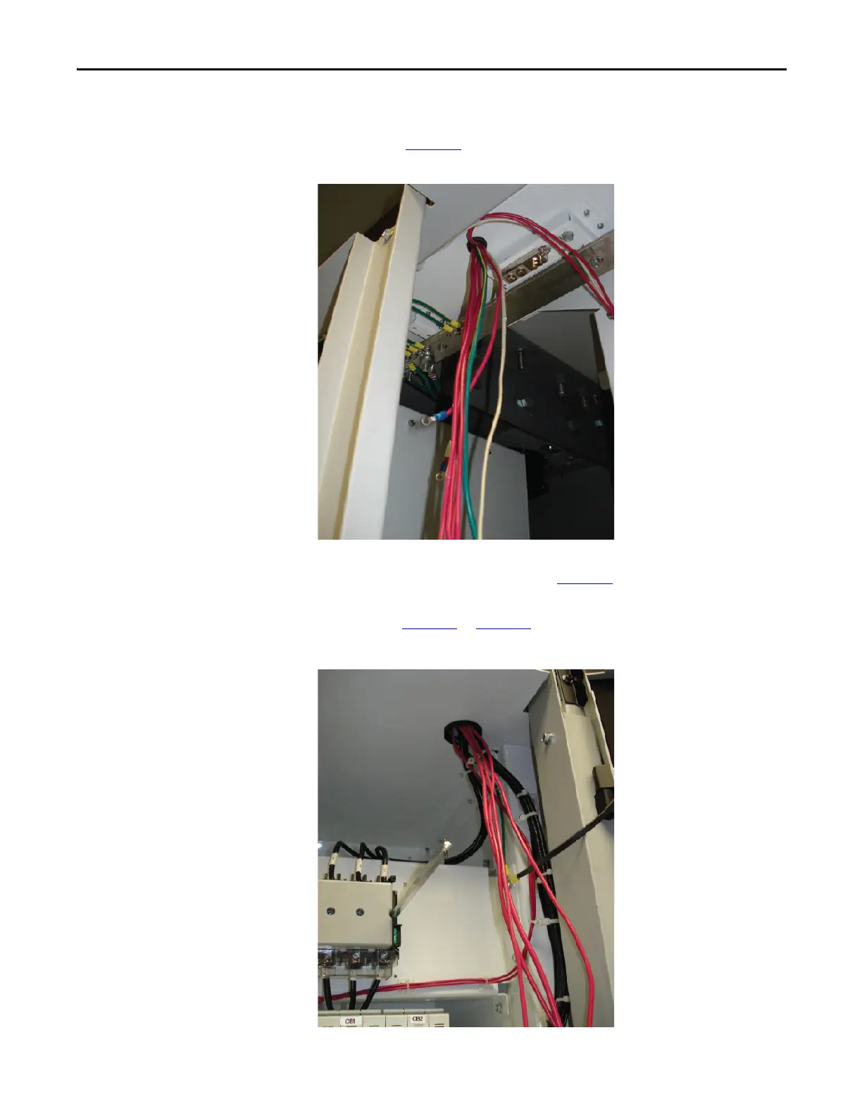
6. Route the control wires down through the grommeted cutout into the
control power disconnect section (Figure 34
).
7. Connect the numbered wires to the corresponding numbered terminal
blocks (Figure 35
to Figure 38).
Figure 34 - Route control wires through grommeted cutout

 Loading...


