Rockwell Automation Publication 7000L-UM301F-EN-P - March 2020 51
Drive Installation Chapter 2
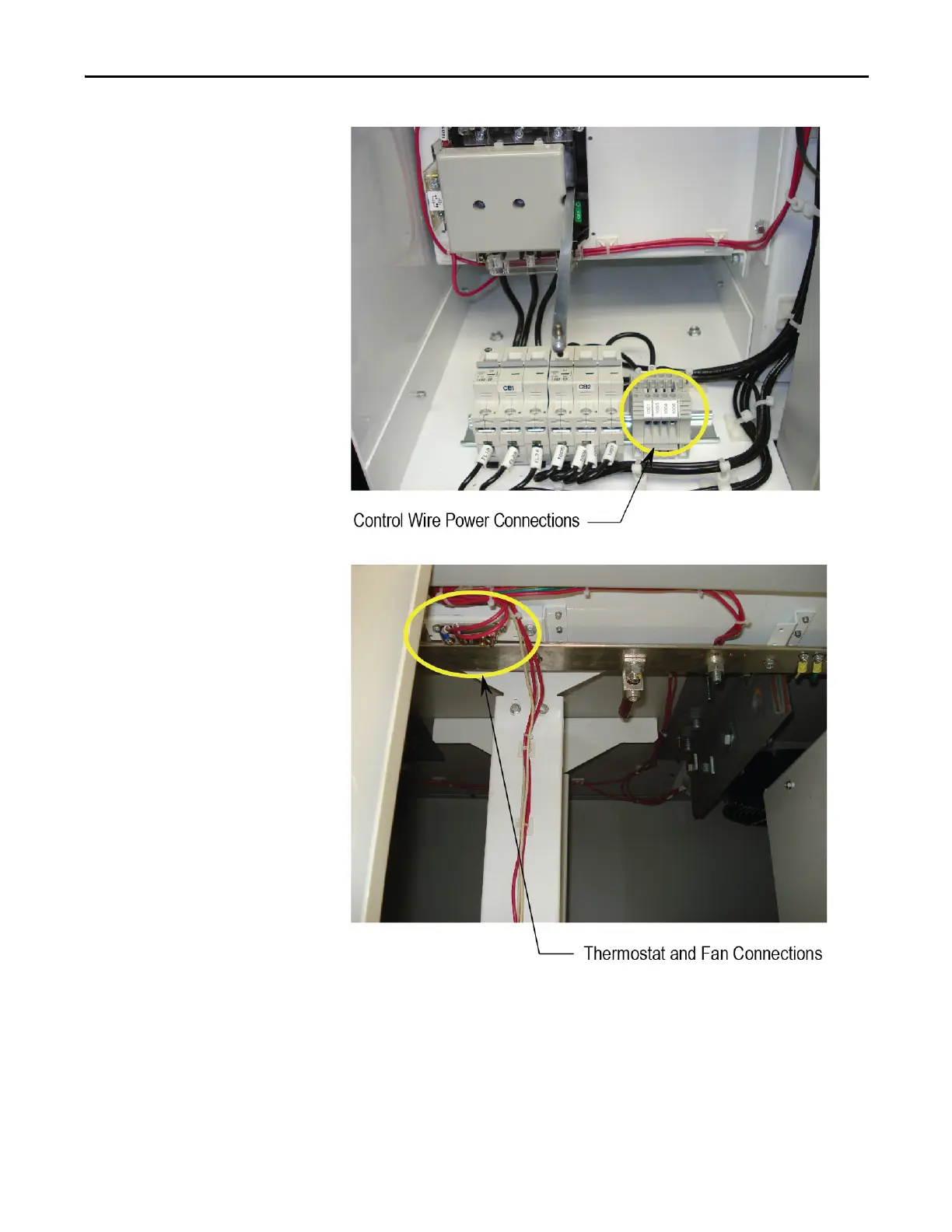
Figure 37 - Control Wire Power Connections
Figure 38 - Thermostat and Fan Connections
9. Once all the connections have been made and neatly routed in each
section, the excess control wires can be looped up in the top wireways.
10. Swing out the control section in the pump control cabinet.
11. Route the XIO link cable, control power wires and the fiber optic cable
down through the wire ways grommeted cutout.
12. Route the XIO link cable, the control power wires into the pump control
cabinet through the upper side grommeted cutout.

 Loading...


