52 Rockwell Automation Publication 7000L-UM301F-EN-P - March 2020
Chapter 2 Drive Installation
13. Route the fiber optic cable into the pump control cabinet through the
lower side grommeted cutout.
Figure 39 - 120V and XIO cables through upper cutout
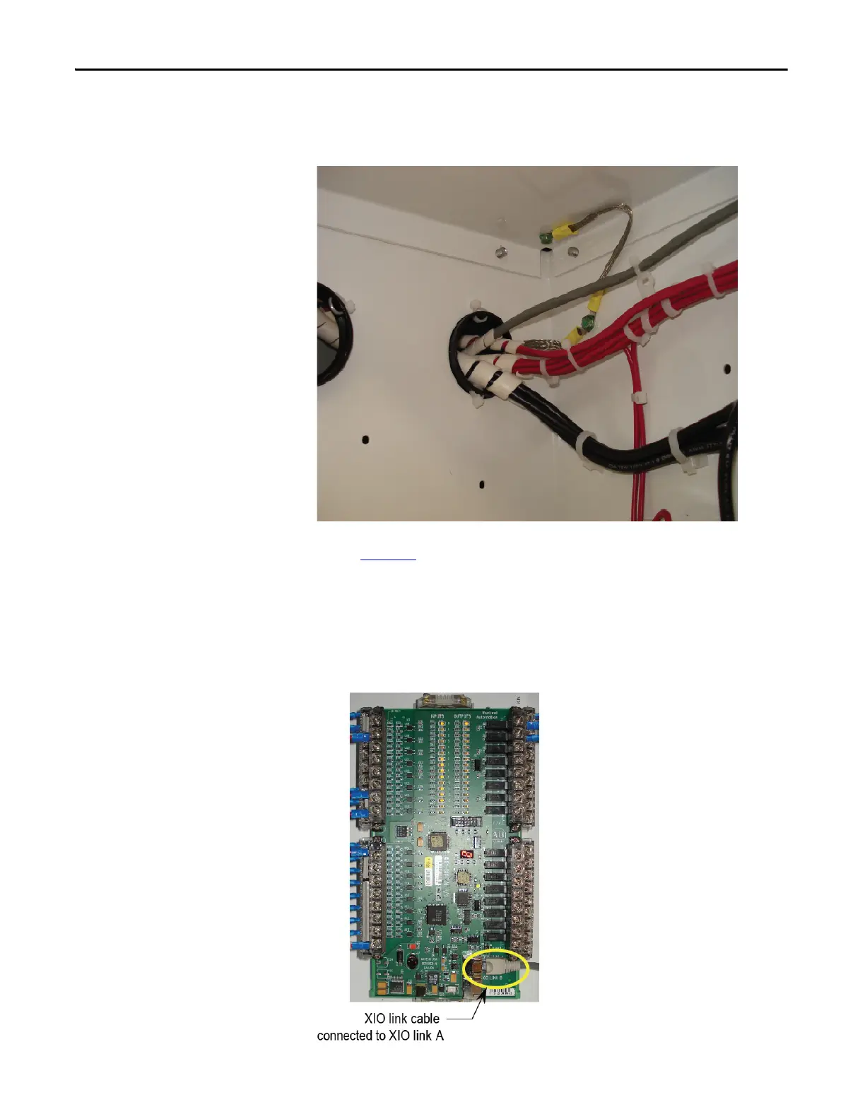
14. Connect the XIO link cable to the XIO board “XIO link A” connector.
(Figure 40
)
15. Connect the control power wires to the control power terminal blocks.
Refer to Electrical Drawings for corresponding wire numbers and terminal
blocks.
16. Connect the fiber optic cable to the TFB board.
Figure 40 - XIO link Cable

 Loading...


