Troubleshooting 9-3
Open Bypass 13, 14, & 15 • Control voltage is low
• Inoperable power module bypass
• Check control voltage power supply
• Replace power module
• Check control module TB2…TB4 and TB5…TB7 for
secureness
• Check Aux 1, 2, 3, 4 configurations are not set to
External Bypass
No Load 16, 17, 18, &
40
• Loss of load side power wiring • Check all load side power connections and motor
windings
Line Unbalance 19 • Supply unbalance is greater than the
user-programmed value
• The delay time is too short for the
application
• Check power system and correct if necessary
• Extend the delay time to match the application
requirements
Overvoltage 20 • Supply voltage is greater than user-
programmed value
• Check power system and correct if necessary
• Correct the user-programmed value
Undervoltage 21 • Supply voltage is less than user-
programmed value
• The delay time is too short for the
application
• Check power system and correct if necessary
• Correct the user-programmed value
• Extend the delay time to match the application
requirements
Overload 22 • Motor overloaded
• Overload parameters are not matched
to the motor
• Check motor overload condition
• Check programmed values for overload class and
motor FLC
Underload 23 • Broken motor shaft
• Broken belts, toolbits, etc.
• Pump cavitation
• Repair or replace motor
• Check machine
• Check pump system
Jam 24 • Motor current has exceeded the user
programmed jam level.
• Correct source of jam
• Check programmed time value
Stall 25 • Motor has not reached full speed by
the end of the programmed ramp time
• Correct source of stall
Phase Reversal 26 • Incoming supply voltage is not in the
expected ABC sequence
• Check power wiring
Coms Loss 27, 28, & 29 • Communication disconnection at the
serial port
• Check for a communication cable disconnection to
the SMC-Flex controller
Network 30, 31, & 32 • DPI network loss • Reconnect for each DPI connected device
Ground Fault 33 • Ground fault current level has
exceeded programmed value
• Check power system and motor; correct if
necessary
• Check programmed ground fault levels to match
application requirements
Excess Starts/Hr. 34 • Number of starts in a one hour period
has exceeded the value programmed
• Wait an appropriate amount of time to restart
• Turn off the Starts/Hr. feature
Power Loss
➀
(with phase
indication)
35, 36,
& 37
• Missing supply phase (as indicated) • Check for open line (i.e., blown line fuse)
Hall ID 38 • Incorrect power module has been
installed
• Check power module and replace
NVS Error 39 • Data entry error • Check user data
• Replace control module
• Reset default values
Line Loss 41, 42, 43 • Line distortion
• High impedance connection
• Check supply voltage for capability to start/stop
motor
• Check for loose connections on line side or motor
side of power wires
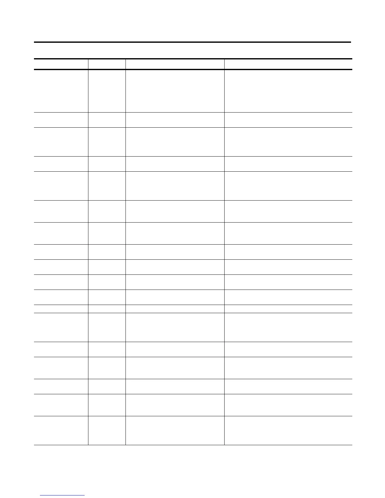
Table 9.A SMC Fault Display Explanation (Continued)
Display Fault Code Possible Causes Possible Solutions

 Loading...


