Wiring 3-11
Control Wire Specifications
Table 3.F provides the control terminal wire capacity, the tightening
torque requirements, and the wire strip length. Each control terminal
will accept a maximum of two wires.
Table 3.F Control Wiring and Tightening Torque
Fan Power Controllers rated 5…1250 A have heatsink fan(s). Refer to Table 3.G
for the control power VA requirements of the heatsink fans.
Fan Terminations
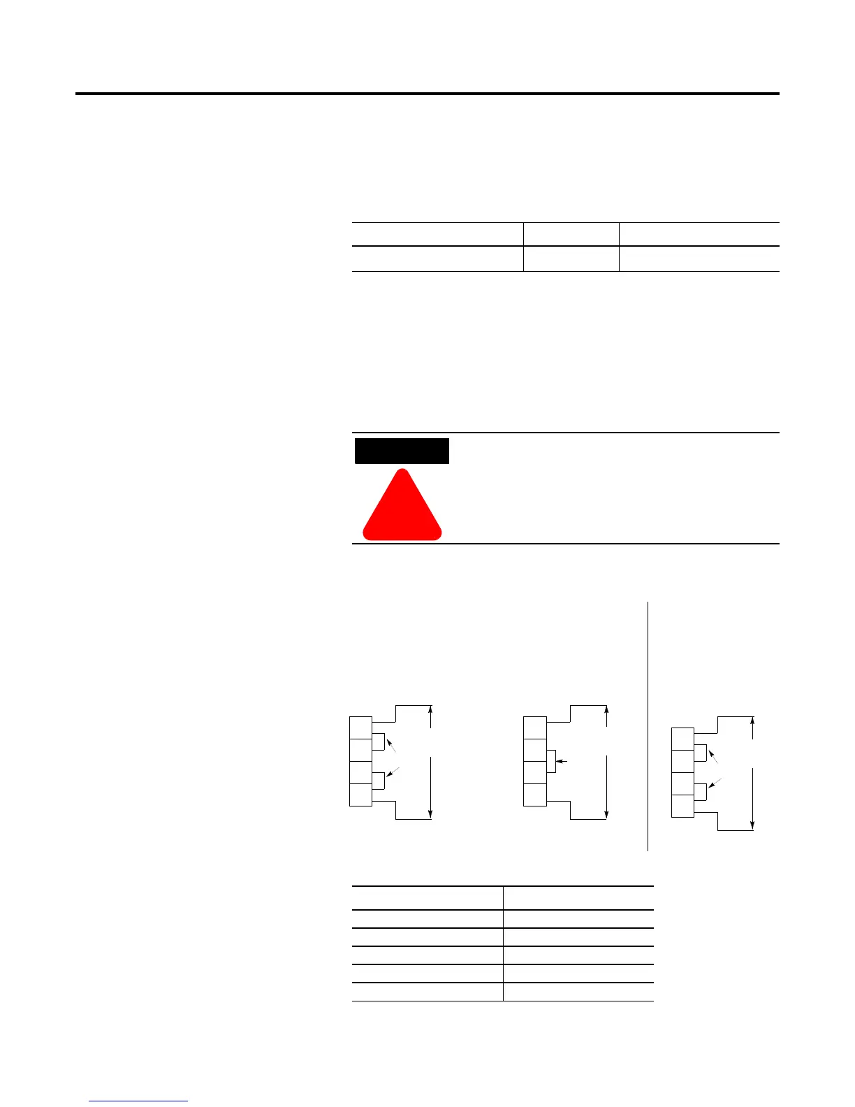
See Figure 3.1, Figure 3.2, and Figure 3.3 for fan power connection
locations.
Figure 3.9 Power Terminations
Table 3.G Heatsink Fan Control Power
➀
Internally wired.
Wire Size Torque Wire Strip Length
0.75…2.5 mm
2
(#18…14 AWG)
0.6 N•m (5 lb.-in.) 5.6…8.6 mm (0.22…0.34 in.)
The fan jumpers have been factory installed for
110/120V AC input. Refer to Figure 3.9 for
220/240V AC fan wiring (5
…480A devices only).
SMC Rating Heatsink Fan VA
5…135 A 20
201…251 A 40
317…480 A 60
625…780 A 150
➀
970…1250 A 150
➀
Factory Set
Optional
220/240 VAC
To
Supply
110/120 VAC
Jumpers
To
Supply
1
2
3
4
5…480 A
625…1250 A
Fan Terminations
Fan Terminations
Control Power/
CP1
110/120 VAC
50/60 Hz ONLY
230/240 VAC
or

 Loading...


