Chapter 3
Wiring
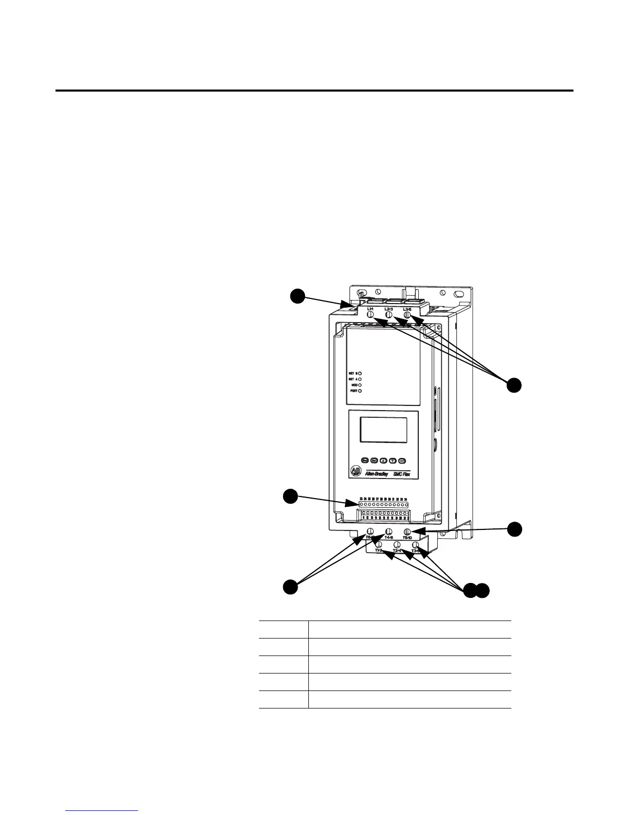
Terminal Locations The SMC-Flex controller wiring terminal locations are shown in
Figure 3.1 and Figure 3.2. Make wiring connections as indicated in
the typical connection diagrams. Incoming three-phase power
connections are made to terminals L1/1, L2/3, and L3/5. Load
connections to Line motors are made to T1/2, T2/4, and T3/6, while
load connections to Wye-Delta motors are made to T1/2, T2/4, T3/6,
T4/8, T5/10, and T6/12.
Figure 3.1 Wiring Terminal Locations (5…85 A)
➀
IP20 protective covers on Delta termination must be removed when connecting in a Delta
configuration.
Table 3.A Wiring Terminal Locations
1 Incoming Line Termination
2 Line Motor Connections
3 Delta Motor Connections
4 Control Terminations
5 Fan Terminations

 Loading...


