3-28 Wiring
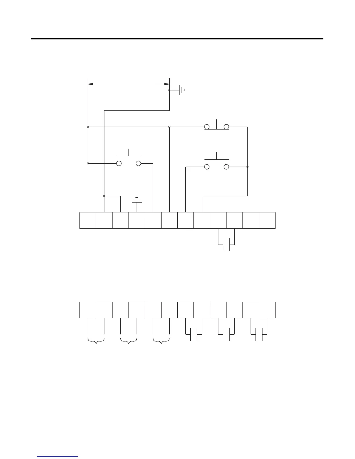
Preset Slow Speed Figure 3.26 and Figure 3.27 show the different wiring for the Preset
Slow Speed.
Figure 3.26 Typical Wiring Diagram for the Preset Slow Speed
➀
Customer supplied.
➁ Refer to the controller nameplate to verify the rating of the control power input voltage.
For units rated 625…1250 A, terminals 11 & 12 are factory pre-wired from terminal block
CP1 - terminals 1 & 4.
➂ Slow Speed.
Note: Refer to Chapter 3 for typical power circuits.
11 12
13
14
15 16
17
18 19 20
21
23
24
25 26
27
28 29
30 31 32 33
22
34
Option Command
Stop
Start
Control Power
Aux #3Aux #2
Aux #4
Aux #1
SMC-Flex
Control Terminals
PTC
Input
TACH
Input
Ground
Fault
➀
➁
➀
➀➂

 Loading...


