3-30 Wiring
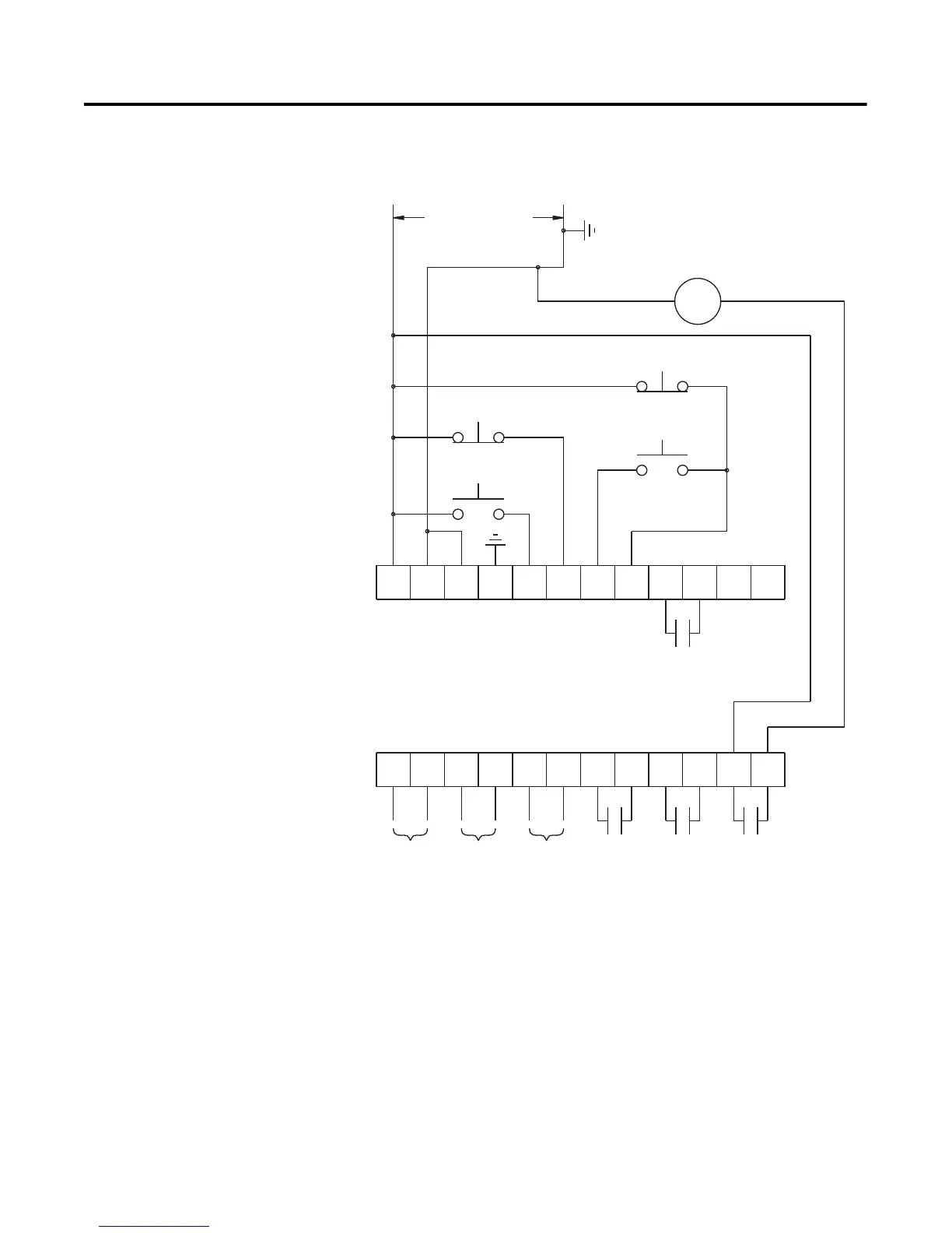
Slow Speed with Braking Figure 3.28 shows the wiring for the Slow Speed with Braking option.
Figure 3.28 Typical Wiring Diagram for the Slow Speed with Braking with an
Isolation Contactor
➀
Customer supplied.
➁ Refer to the controller nameplate to verify the rating of the control power input voltage.
For units rated 625…1250 A, terminals 11 & 12 are factory pre-wired from terminal block
CP1 - terminals 1 & 4.
➂ Aux #4 should be set to normal operation.
Note: Refer to Chapter 3 for typical power circuits.
3LOW3PEED
3TOP
3TART
#ONTROL0OWER
"RAKE
!UX!UX
!UX
!UX
3-#&LEX
#ONTROL4ERMINALS
)#
04#
)NPUT
4!#(
)NPUT
'ROUND
&AULT
➂

 Loading...


