Chapter 3 Modes of Operation
MC9S08QE128 MCU Series Reference Manual, Rev. 2
48 Freescale Semiconductor
3.7.1 On-Chip Peripheral Modules in Stop and Low Power Modes
When the MCU enters any stop mode, system clocks to the internal peripheral modules are stopped. Even
in the exception case (ENBDM = 1), where clocks to the background debug logic continue to operate,
clocks to the peripheral systems are halted to reduce power consumption. Refer to Section 3.6.1, “Stop2
Mode,” and Section 3.6.2, “Stop3 Mode,” for specific information on system behavior in stop modes.
When the MCU enters LPWait or LPRun modes, system clocks to the internal peripheral modules continue
based on the settings of the clock gating control registers (SCGC1 and SCGC2).
5
LPWAIT RUN
Interrupt when LPWUI=1
RUN LPWAIT
NOT SUPPORTED
6
RUN WAIT
WAIT instruction
WAIT RUN
Interrupt or reset
7
STOP3 RUN
Interrupt (if LPR = 0, or LPR = 1 and LPWUI =1)
or reset
RUN STOP3
STOP instruction
1
An analog connection from this pin to the on-chip regulator will wake up the regulator, which will then initiate a
power-on-reset sequence.
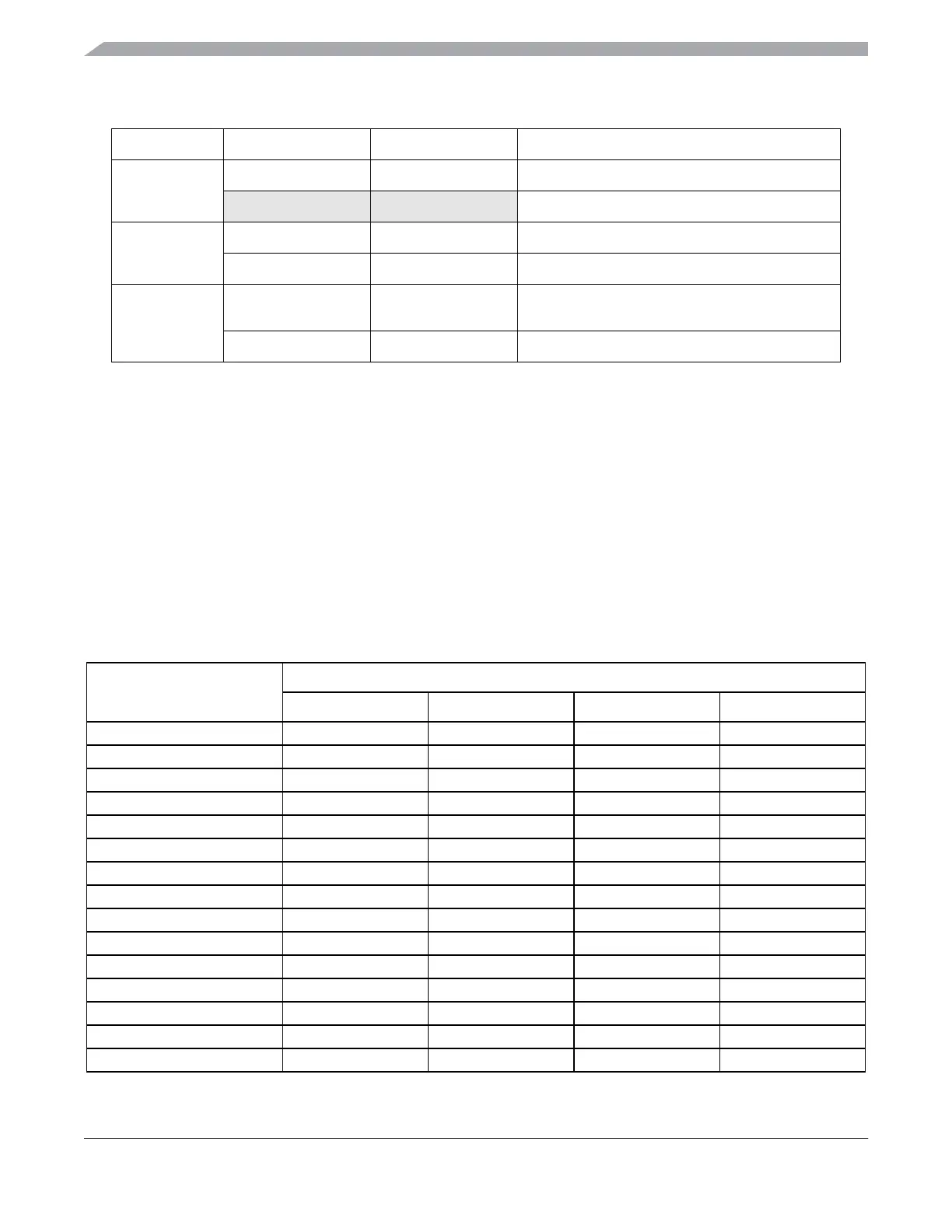
Table 3-4. Stop and Low Power Mode Behavior
Peripheral
Mode
Stop2 Stop3 LPWait LPRun
CPU Off Standby Standby On
RAM Standby Standby Standby On
Flash Off Standby Standby On
Port I/O Registers Off Standby Standby On
Port I/O Pins States Held Peripheral Control Peripheral Control On
ADC Off Optionally On
1
Optionally On
1
Optionally On
1
ACMPx Off Optionally On
2
Optionally On Optionally On
BDM Off
3
Optionally On Off
4
Off
4
COP Off Off Optionally On Optionally On
ICS Off Optionally On
5
On
6
On
6
IICx Off Standby Optionally On Optionally On
IRQ Wake Up Optionally On Optionally On Optionally On
KBIx Off Optionally On Optionally On Optionally On
LVD/LVW Off
7
Optionally On Off
8
Off
8
RTC Optionally On Optionally On Optionally On Optionally On
Table 3-3. Triggers for Transitions Shown in Figure 3-1. (continued)
Transition # From To Trigger