Chapter 3 Modes of Operation
MC9S08QE128 MCU Series Reference Manual, Rev. 2
Freescale Semiconductor 47
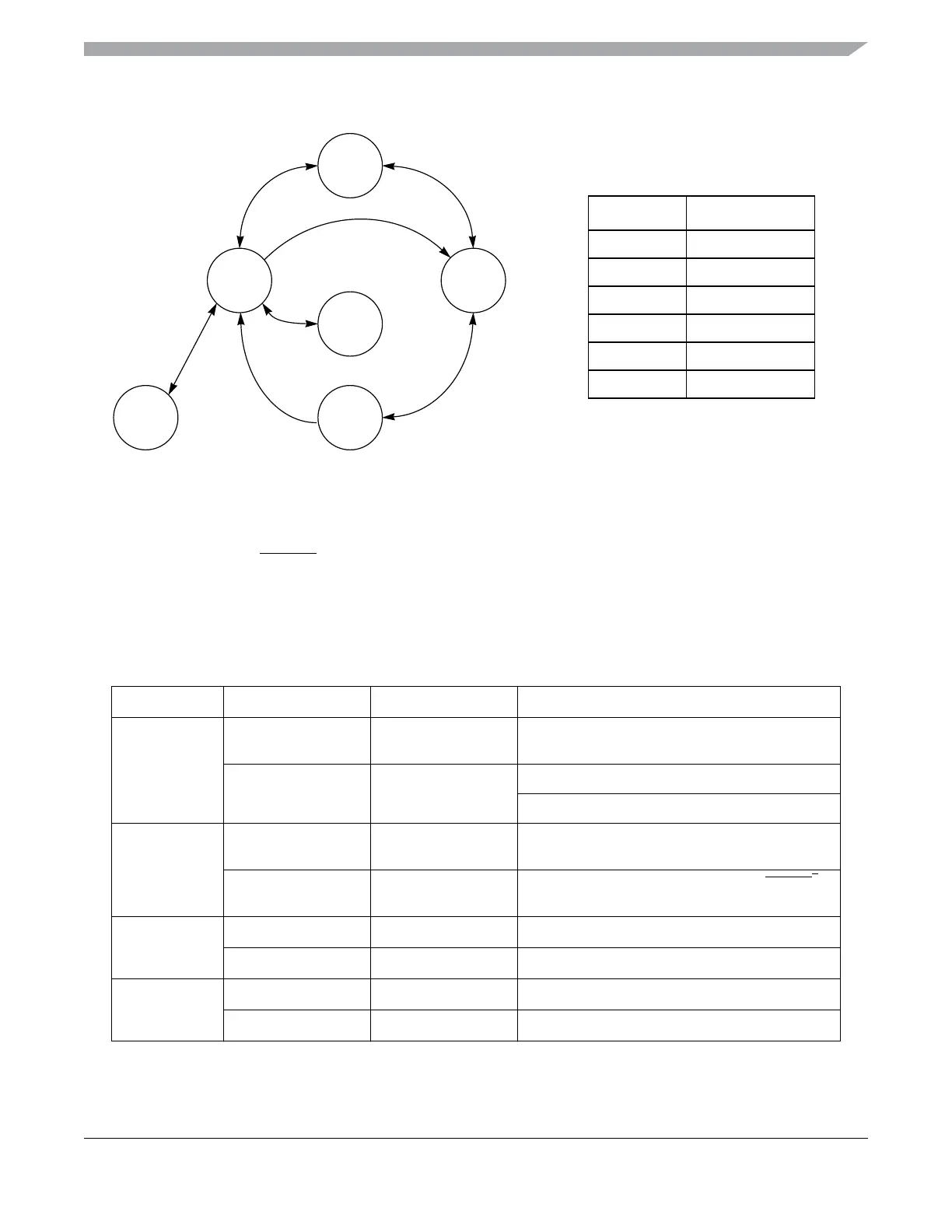
Figure 3-1. Allowable Power Mode Transitions for the MC9S08QE128 Series
Figure 3-1 illustrates mode state transitions allowed between the legal states shown in Table 3-1.
PTA5/IRQ/TPM1CLK/
RESET must be asserted low (or an RTC interrupt must occur) in order to exit
stop2. Interrupts suffice for the other stop and wait modes.
Table 3-3 defines triggers for the various state transitions shown in Figure 3-1.
Table 3-3. Triggers for Transitions Shown in Figure 3-1.
Transition # From To Trigger
1
RUN LPRUN
Configure settings shown in Table 3-1, switch
LPR=1 last
LPRUN RUN
Clear LPR
Interrupt when LPWUI=1
2
RUN STOP2
Pre-configure settings shown in Table 3-1, issue
STOP instruction
STOP2 RUN
Assert zero on PTA5/IRQ/TPM1CLK/RESET
1
,
reload environment from RAM
3
LPRUN LPWAIT
WAIT instruction
LPWAIT LPRUN
Interrupt when LPWUI=0
4
LPRUN STOP3
STOP instruction
STOP3 LPRUN
Interrupt when LPWUI=0
Mode Regulator State
RUN Full on
WAIT Full on
LPRUN Standby
LPWAIT Standby
STOP3 Standby
STOP2 Partial power off
STOP3
STOP2
LPWAIT
LPRUNRUN
WAIT
74
1
3
5
2
6