Installation
Quantum Intelligent EV Charging Pedestal EVQM-V01-R6 Installation and Operation Manual
Page 23 of 52 December 2023
If installing at a later date, work may be required to enable entry of the CT cable into the
pedestal enclosure.
Overview
Power coming into the property is monitored by a Current Transformer (CT) that clamps
around the property’s incoming power cable and is then connected to the chargepoint.
x The CT has a cable allowing it to be connected to the chargepoint.
x Additional cable may be added to the CT cable but to maintain a good signal, it is
recommended that cables extensions are kept as short as possible.
Connect the CT to the Property
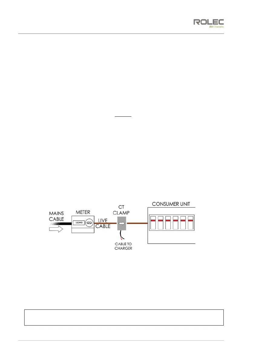
1. The CT clamp should be positioned around the Live (positive) cable between the
Meter and the Consumer Unit.
2. The arrow shown on the CT clamp must point in the direction of electrical flow
TOWARD the consumer unit.
x Alternatively, if required, the CT clamp may be positioned on the Negative
cable leaving the Consumer Unit. The arrow on the CT clamp must point in the
direction of electrical flow AWAY from the consumer unit.
3. Release the clip on the CT clamp then open the clamp.
4. Place the CT clamp around the power cable.
x Make sure the arrow on the clamp points in the correct direction.
x No other cables should pass though the CT clamp.
5. Close the CT clamp and secure it with the clip.
Figure 16 CT Clamp Positioning
Extend the CT Cable
1. If required, the CT cable may be extended up to a theoretical maximum of 100m.
2. To avoid interference and reduce the loss of signal, extension cables should be as
short as possible. Extensions of 20m or less are recommended.
3. Extension cables must be a screened ‘Twisted Pair’. A screened twisted pair within
a CAT6 computer network cable may be used.
NOTE: Twisted pairs within a CAT cable are indicated by their matching colours.
Do NOT use conductors of different colours, interference may be induced.