Installation
EVQM-V01-R6 Installation and Operation Manual Quantum Intelligent EV Charging Pedestal
December 2023 Page 24 of 52
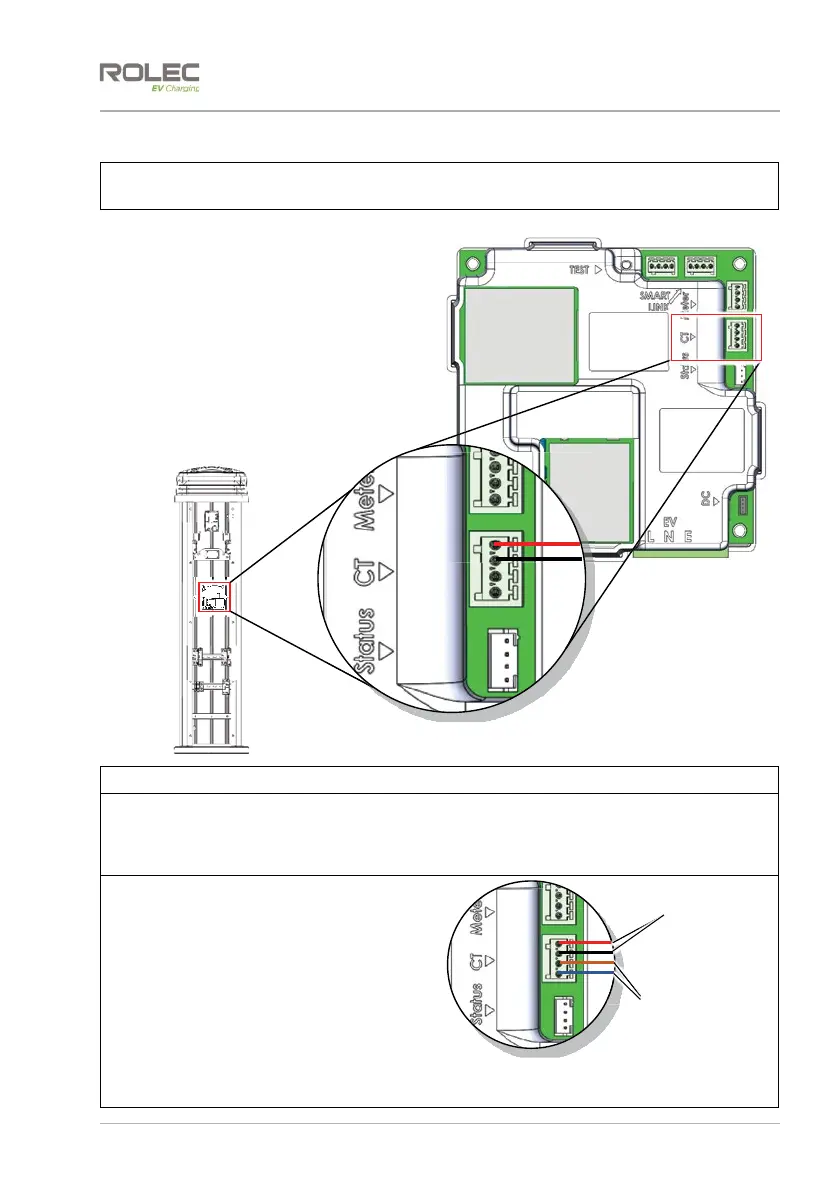
Connect the CT Cable to the Chargepoint
IMPORTANT: A suitable cable gland must be installed to the chargepoint enclosure to
accept the CT cable and maintain the IP rating of the enclosure.
1. Locate the EV Charge Controller
enclosure and the connector
marked CT.
2. Connect one CT clamp wire to the
H+ terminal on the circuit board
connector.
3. Connect the other CT clamp wire to
the H- terminal on the circuit board
connector.
x The CT wires do not have a
polarity.
Figure 17 Load Balancing CT Connection
NOTE: The EV Charge Controller may be in a different orientation to that shown above.
NOTE: 4-way chargers are essentially 2x 2-way chargers in one pedestal. One or both ‘sides’
of the pedestal can use load balancing and will operate independently to each other.
Assuming the power supply is sufficient, if only one side is load balanced, the other side will
always receive full power which may be useful if needing priority charging.
NOTES:
1. If extending the CT cable or adding
a solar monitoring CT, the cable
colours will be those that you have
chosen to use.
2. The lower two terminals on the CT
connector may be used to attach a
CT used with a solar system.
Figure 18 CT Connections for Load Balancing
and Solar Monitoring
S-
S+
H-
H+
Load Balancing
Connections
Solar Monitoring
Connections