Page | 42
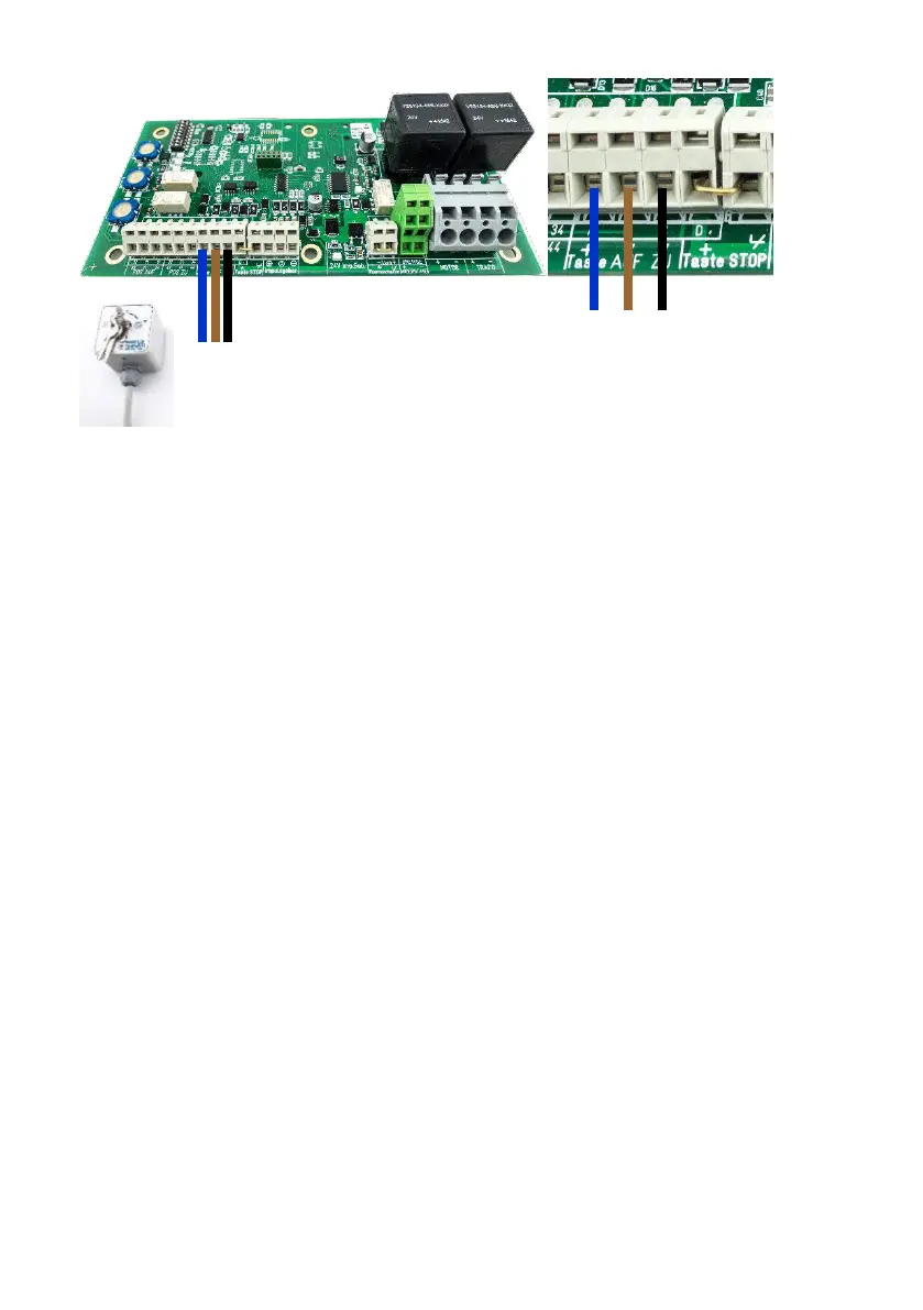
8. Connect the key switch cables to the circuit board as shown in the image.
a. Circuit board terminal ‘+’ with the cable terminal position ‘P’ of the key
switch
b. Circuit board ‘AUF’ (OPEN) with cable terminal position ‘1’ of the key
switch
c. Circuit board ‘ZU’ (CLOSED) with cable terminal position ‘2’ of the key
switch
Please note: If the winding directions of the circuit board and switch do not correspond
to one another, the connections for the ‘AUF’ and ‘ZU’ switch on the control board must
be swapped.