Reference Manual
00809-0100-4738, Rev DA
May 2006
Rosemount 3095FB
4-10
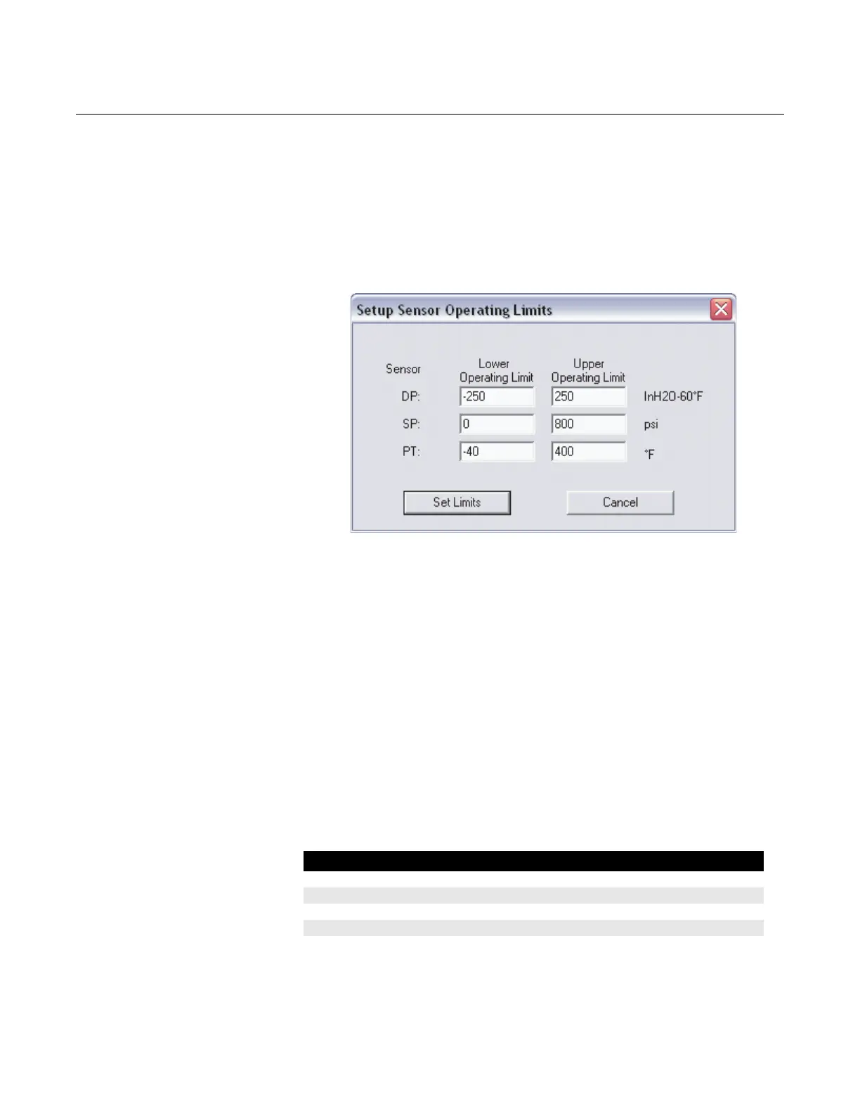
Setup > Sensor Limits…
This screen determines the normal sensor operating limits for each of the
process variables. If a process value is outside of these set limits, the
appropriate alarm status bit will be set (registers 407, 408, or 409. See
section 8.0 in Modbus Protocol Guide in chapter 3).
Figure 4-8. Sensor Limits Screen
Setup > Data Formats…
Floating Point Format:
• Byte Transmission Order: Specifies the byte order for the transmission
of IEEE 754 floating point numbers. Changing the byte transmission
order only affects the transmission of data that is in floating point form,
not integer form. Changing the byte order may be necessary to make
sure that floating point numbers are compatible between the 3095FB
transmitter and the Modbus host system.
IEEE floating point numbers are made up of 4 bytes (total of 32 bits).
The 3095FB can transmit floating point numbers in 4 different byte
formats. The default and additional formats are shown in Table 4-3.
For more information, refer to section 3.4 in the Modbus Protocol Guide
in chapter 3.
Table 4-3. Available Floating Point Formats
Floating Point Format Code Byte Transmission Order Example Number
Format 0 (default) A B C D $42 C8 80 00
Format 1 C D A B $80 00 42 C8
Format 2 D C B A $00 80 C8 42
Format 3 B A D C $C8 42 00 80