Reference Manual
00809-0100-4738, Rev DA
May 2006
Rosemount 3095FB
2-19
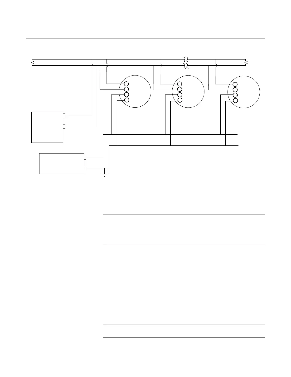
Figure 2-14. RS-485 Multidrop Topology
HAZARDOUS
LOCATIONS
The Rosemount 3095FB Transmitter has explosion-proof housing and
circuitry. Individual transmitters are clearly marked with a tag indicating the
certifications they carry. See Appendix B for specific approval categories and
installation drawings.
NOTE
Once a device labeled with multiple approvals is installed, it should not be
reinstalled using any other approval type(s). Permanently mark the
certification label to distinguish the installed approval type from unused
approval types.
Grounding the
Transmitter Case
The transmitter case should always be grounded in accordance with national
and local electrical codes. The most effective transmitter case grounding
method is direct connection to earth ground with minimal impedance.
Methods for grounding the transmitter case include:
• Internal Ground Connection: The Internal Ground Connection screw
is inside the FIELD TERMINALS side of the electronics housing. This
screw is identified by a ground symbol, and is standard on all
Rosemount 3095FB transmitters.
• External Ground Assembly: This assembly is included with the
transient protection terminal block. The External Ground Assembly can
also be ordered as a spare part (03031-0398-0001).
NOTE
Do not ground the RS-485 bus at any point on the bus.
RS-485 Bus
B
User-Provided
Power Supply
-
+
A
B
+
-
RS-485
PWR
A
B
+
-
RS-485
PWR
RTU
B
A
Rosemount
3095FB
Rosemount
3095FB
Twisted pair not required
. . .
A
A
B
+
-
RS-485
PWR
120 ohm
120
ohm
Rosemount
3095FB
Twisted pair required