Reference Manual
00809-0100-4738, Rev DA
May 2006
Rosemount 3095FB
2-9
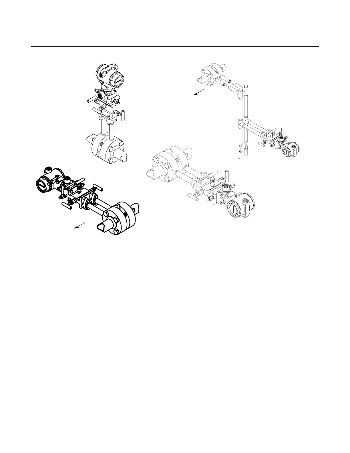
Figure 2-4. Example Installations
Process Connections The 3095 process connections on the transmitter flange are 1/4–18 NPT.
Flange adapter unions with 1/2–14 NPT connections are available as options.
These are Class 2 threads; use your plant-approved lubricant or sealant when
making the process connections. The process connections on the transmitter
flange are on 2
1
/8-inch (54-mm) centers to allow direct mounting to a three- or
five-valve manifold. By rotating one or both of the flange adapters, connection
centers of 2, 2
1
/8, or 2
1
/4 inches (51, 54, or 57 mm) may be obtained.
Install and tighten all four flange bolts before applying pressure or process
leakage will result. When properly installed, the flange bolts will protrude
through the top of the module housing. Do not attempt to loosen or remove
the flange bolts while the transmitter is in service.
Flow
Flow
3095\3095b03b, 3095d03b
GAS SERVICE
LIQUID SERVICE
Flow
STEAM
SERVICE