00809-0100-4835 Rev BD
2-5
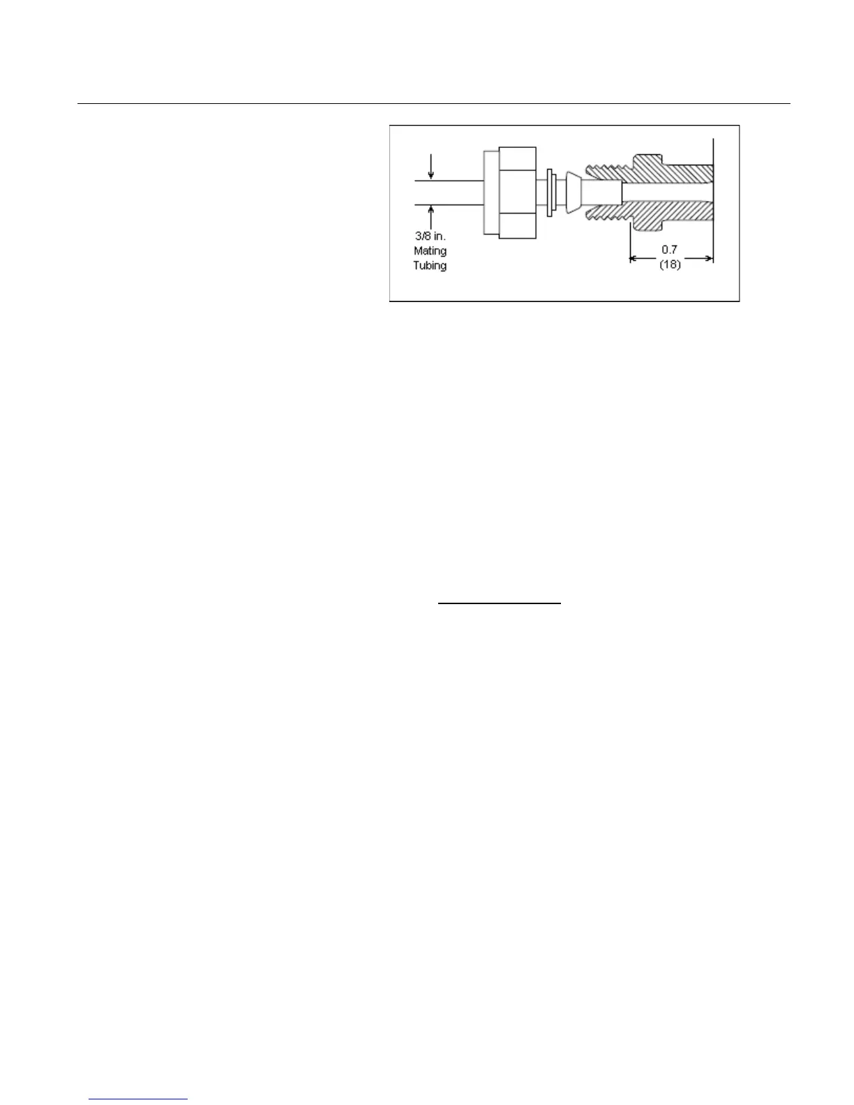
Figure 2-1 – Swagelok™
Compression Fitting Detail
The Swagelok™ tube fittings come completely assembled and are
ready for immediate use.
Do not disassemble them before use
because dirt or foreign materials may get into the fitting and cause
le
aks. Insert the tubing into the Swagelok™ tube fitting, make sure the
tubing rests firmly on the shoulder of the fitting and the nut is finger
tight. Tighten the nut one
-and-one-quarter turns. Do not over-tighten.
To reconnect, insert the tubing with p
re-swaged ferrules into the fitting
until the front ferrule sits in the fitting. Tighten the nut by hand, then
rotate one
-quarter turn more or to the original one-and-one-quarter tight
position. Then snug it slightly with a wrench.
nformation regarding the specifications and use of
Swagelok™ tube fittings, refer to:
Fittings Catalog MS-01-140
“Gaugeable Tube Fittings and Adapter Fittings”
www.swagelok.com
If drain/vent valves are opened to
bleed process lines, torque stems to
-2 in Section 5 Maintenance and Troubleshooting
The piping between the process and the transmitter must accurately
transfer the pressure to obtain accurate measurements. There are fi
ve
possible sources of error: pressure transfer (such as obstruction), leaks,
friction loss (particularly if purging is used), trapped gas in a liquid line
or liquid in a gas line and density variations between the legs.
The best location for the transmit
ter in relation to the process pipe
depends on the process itself. Use the following guidelines to
determine transmitter location and placement of impulse piping:
• Keep impulse piping as short as possible
• For liquid service, slope the impulse piping at least 1 inch per
foot (8 cm per m) upward from the transmitter toward the
process connection
• For gas service, slope the impulse piping at least 1 inch per foot
(8 cm per m) downward from the transmitter toward the process
connection
• Avoid high points in liquid lines and low points in gas lines
• Make sure both impulse legs are the same temperature
Dimensions are nominal in inches (mm)