00809-0100-4835 Rev BD
2-8
ELECTRICAL
CONSIDERATIONS
This section contains information you should consider when preparing
to make electrical connections to the transmitter. Read this section
carefully before proceeding to the electrical installation procedure.
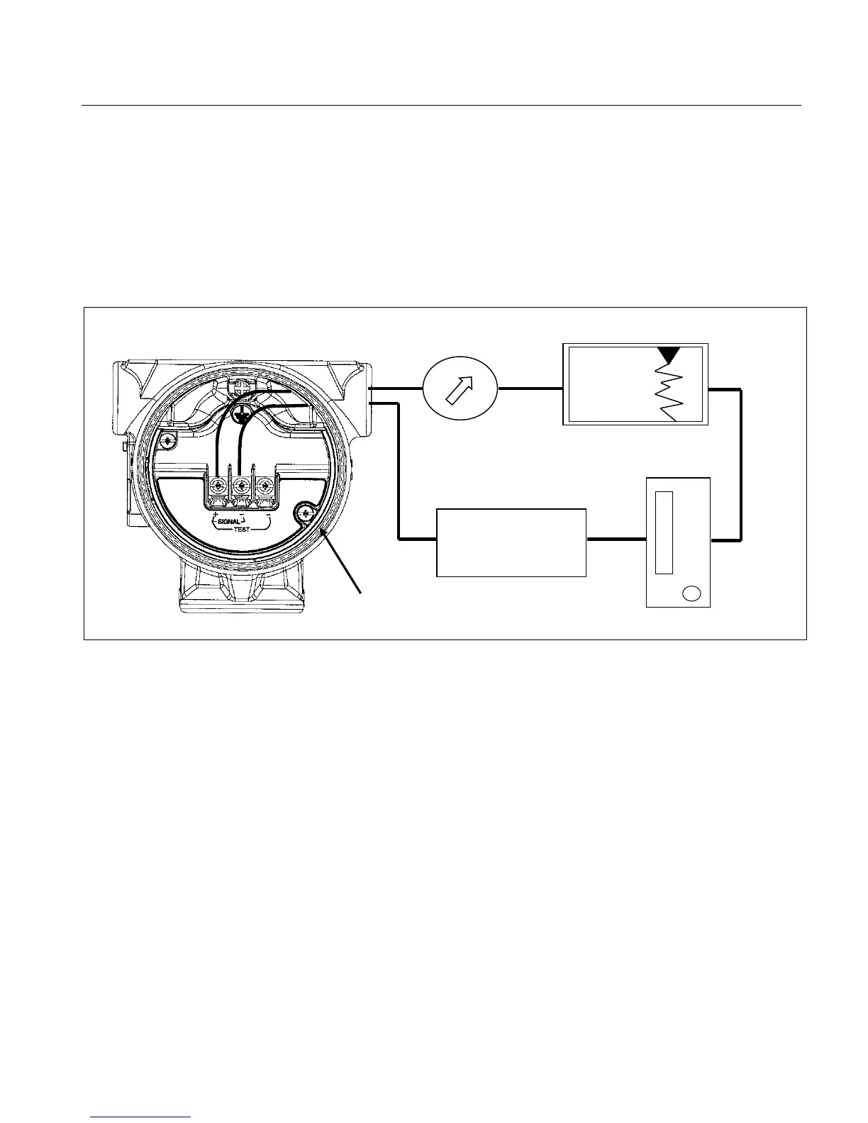
Rosemount 3150 Series transmitters provide a 4-20 mA signal when
connected to a suitable dc power source. Figure 2-3 illustrates a typical
signal loop consisting of a transmitter, power supply, and various
receivers (controller, indicator, computer).
Figure 2-3 – Typical transmitter
Wiring connection
The power supply must supply at least 12 volts to the transmitter
terminals at 20 mA signal, or the maximum output current required for
proper system operation. Any power supply ripple appears in the
output load. The power supply versus load limitation relationship is
shown in Figure 2-4. See qualification reports for additional details.
The loop load is the sum of the resistance of the signal leads and the
load resistance of the receivers.
Terminal Side (cover removed)
Supply