00809-0100-
5-11
NOTE
Numbers in parentheses refer to item numbers in Figure 5-1.
3150 Series transmitters contain electronic circuit boards which may
be static sensitive. Therefore, observe proper ESD
precautions/techniques whenever the electronics assemblies are
Reassembly
The Electronics Housing (5), Housing Set Screws (12) and
Sensor Module (8) Assembly cannot be disassembled in the
field. The Housing Set Screws (12) are held in place by a thread lock
compound (Loctite
®
266) applied at the factory during manufacturing.
If this interface is damaged, the qualification of the transmitter
becomes invalid. The following reassembly instructions assume that
the housing-to-module interface is intact. For any maintenance that
requires the sensor module (8) be removed from the housing (5),
please contact Rosemount Nuclear Instruments, Inc.
1. Replace the cover o-rings (2) whenever removing an electronics
housing cover (1). Check the cover o-ring grooves for
cleanliness. If chips or dirt are present, clean the seat and
mating portion of the cover with alcohol. Lubricate replacement
o-ring(s) with Molykote
®
55 silicone o-ring grease or your plant-
approved equivalent. For reference, the transmitter was qualified
using Molykote
®
silicone o-ring grease (RNII P/Ns 03154-5002-
0001 or 03154-5002-0002).
2. Ensure filter pins are clean. If necessary, clean with alcohol.
Electronics Assembly Installation
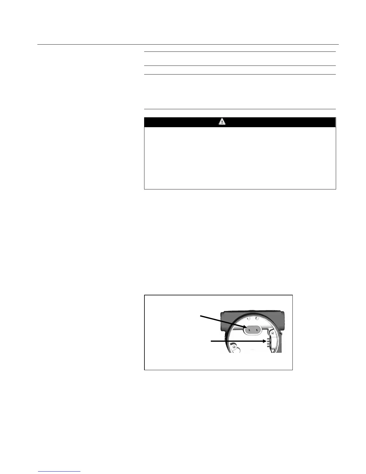
1. Align the zero and span adjustment screws with the
potentiometer stems on the board in the electronics assembly (4)
Figure 5-6 – Alignment of Adjustment
Screws and Potentiometer Stems
proper installation of
electrical assembly