00809-0100-4835 Rev BD
2-7
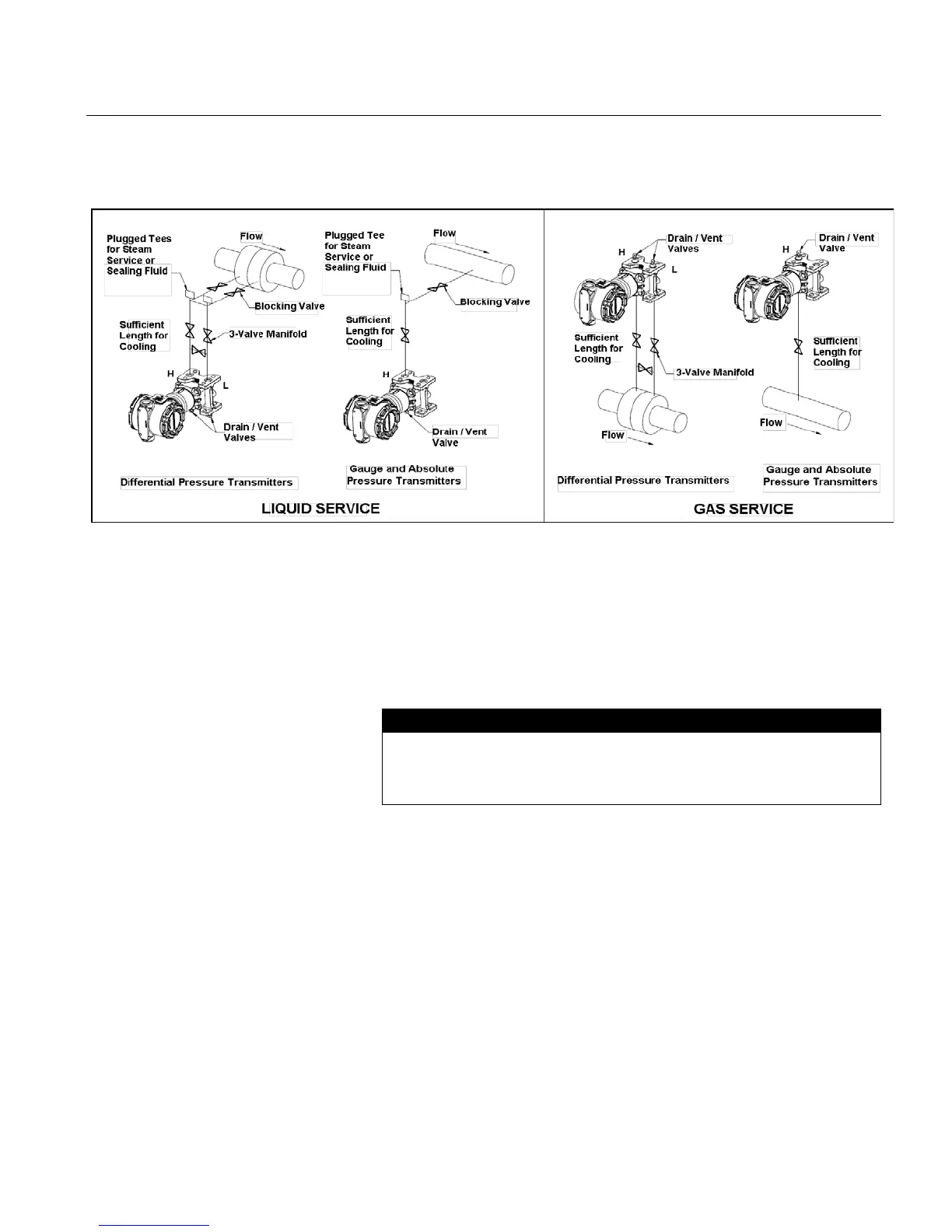
Figure 2-2 Transmitter Installation
Examples (liquid, gas or steam)
Please note that transmitters depicted in Figure 2-2 are intended for reference only.
Conduit
Electrical Housing
The conduit connections to the transmitter are threaded. Options
available are ½ -14 ANPT, M20, PG 13.5 and G1/2. Two openings are
available on the 3152 and 3153 transmitter housings for convenient
installation. Close of
f the unused opening with a compatible thread type
stainless steel pipe plug. Use your plant-approved, qualified thread
sealant on the conduit connection threads.
For all 3152 and 3153 transmitters, install the conduit plug (provided
with
the transmitter) in the unused conduit opening per the torque
Section 5: Maintenance and Troubleshooting,
The 3154 has one conduit connection.
Use a qualified conduit seal at the conduit entry to prevent moisture
from accumulating in the terminal side of the housing during accident
conditions. Certain option codes provide a qualified connector with the
connector factory assembled to the transmitter. To prevent the conduit
from adding mechanical stress to the transmitter during seismic
disturbances, use flexible conduit or support the conduit near the
transmitter. Install the conduit seal in accordance with the
manufacturer’s instructions or use the procedure in this section.
The standard transmitter orientation is shown in dimensional drawings
found in this manual (see Figure 2-6). The electronics housing
cannot be rotated in the field. For more information, please contact
Rosemount Nuclear Instruments, Inc.