00809-0100-4835 Rev BD
2-10
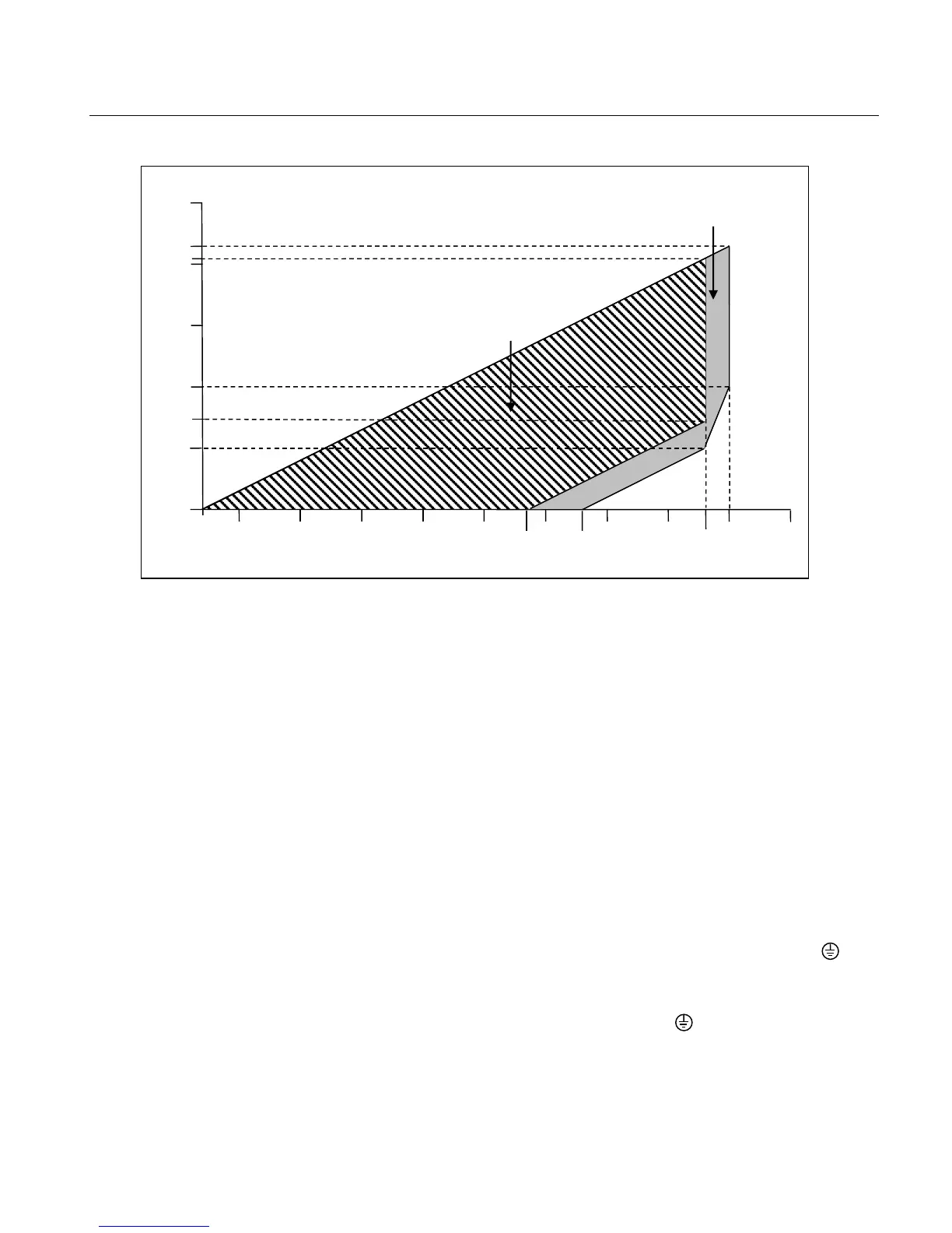
Figure 2-4c – RCC-E Qualified and Design Regions
(applicable to 3153K and 3154K models only)
Signal wiring need not be shielded, but twisted pairs yield the best
results. Shielded cable should be used for best results in electrically
noisy environments. Do not run signal wiring in conduit or open trays
with AC power wiring, or near heavy electrical equipment. Signal wiring
may be ungrounded (floating) or grounded at any one point
loop.
For installations with EMC performance requirements, consult the
Rosemount Nuclear Instruments, Inc. EMC test reports for additional
details regarding recommended practices for electrical wiring per
various national and international codes and regulations.
The transmitter case may be grounded or ungrounded. Grounding
should be completed in accordance with national and local electrical
codes. Transmitter case can be grounded using either the internal or
external ground connection.
• Internal Ground Connection: The Internal Ground
Connection screw is inside the terminal side of the electronics
housing. The screw is identified by a ground symbol (
is standard on all 3150 Series transmitters.
• External Ground Assembly: The External Ground location is
indicated by the ground symbol ( ) on the module. An
External Ground Assembly kit can be ordered as an option on
the 3150 Series transmitter. This kit can also be ordered as a
spare part. Please contact RNII for ordering information.
QUALIFIED
REGION