00809-0100-
5-15
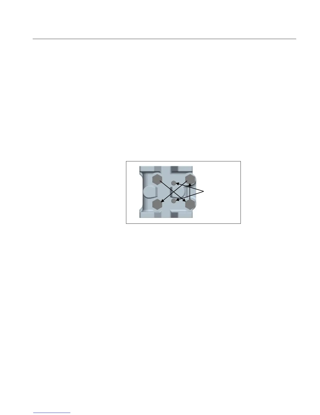
3. With the process flange sitting secure on the sensor module,
install two flange cap screws (13) into the flange location shown
in Figure 5-12. Tighten the cap screws approximately two or
three rotations only.
4. Place the four bolts (11) through the process flange and screw
them on finger-tight.
5. Using a hand torque wrench, evenly seat the flange onto the
sensor module by following steps 6 through 9 (see Figure 5-12 to
identify the bolts).
6. Alternately tighten the four bolts in the sequence shown in Figure
5-12 to 150 in-lbs ±15 in-lbs (16.9 N-m ± 1.7 N-m)
7. Repeat step 6.
8. Repeat step 6 at 300 in-lbs ± 25 in-lbs (33.9 N-m ± 2.8 N-m)
9. Repeat step 8.
10. Torque the two cap screws in the flange to 33 in-lbs ± 1.7 in-lbs
(3.7 N-m ± 0.2 N-m). NOTE: Cap screws must be torqued after
bolts, or they will loosen.
Figure 5-12 – Flange Bolt Torqueing
Sequence