d05785.fm
INSTALLATION MANUAL
BRP-Powertrain
Effectivity: 912 i Series
Edition 1/Rev. 0
75-00-00
Page 13
January 01/2012
Graphic
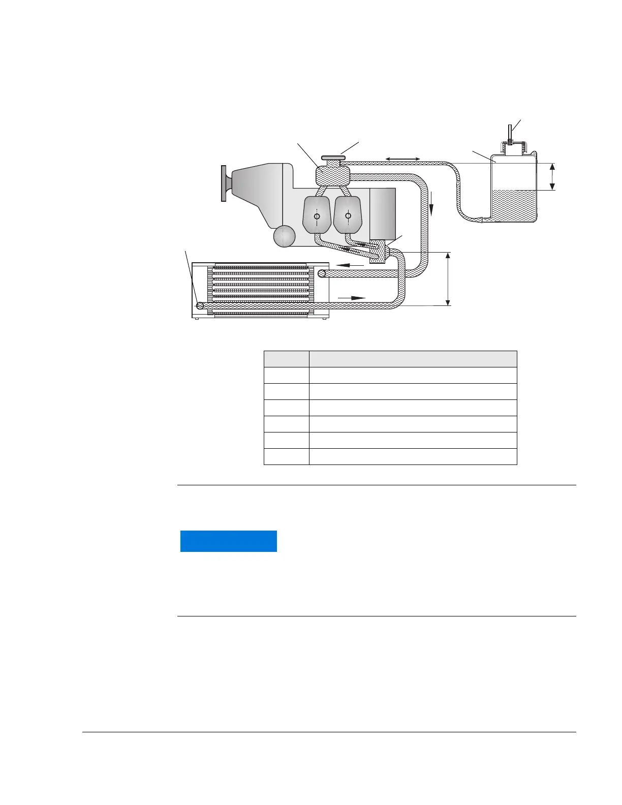
Permitted installation positions
Fig. 7 08319
Overflow bottle The system also needs an overflow bottle in which surplus coolant is col-
lected and returned to the coolant circuit during the cooling down period.
NOTE: For proper operation ensure that the hose to the overflow
bottle is as short as possible.
Part Function
1 Expansion tank
2 Pressure cap
3 Radiator outlet
4 Water inlet elbow
5 Overflow bottle
6 Purging
max. 250mm /
max. 9.84 in.
max. 1,5 m /
max.
59.05 in.
To ensure proper operation of the cooling system, the
suction height between overflow bottle and expansion
tank must not exceed 250 mm (10 in.).

 Loading...


