d05781.fm
INSTALLATION MANUAL
BRP-Powertrain
Effectivity: 912 i Series
Edition 1/Rev. 2
24-00-00
Page 19
January 01/2014
5) Wiring harness
The wiring harness connects the engine control and the
- Control unit (ECU)
- FUSE BOX assy.
- Cockpit (switch, instruments, maintenance connection)
- Engine (sensors, injectors, ignition coils)
Sensors The sensors are fitted by BRP-Powertrain and connected to the wiring
harness. The exhaust gas temperature sensors are included according to
the version or already fitted on GENUINE-ROTAX exhaust systems.
ECU/FUSE BOX
connector
Install and lock the connectors of the ECU and/or FUSE BOX with gas-
ket.
NOTE: Connectors with gasket difficult to push/pull.
HIC The HIC (Harness Interface Connectors) connects the cockpit instru-
ments and maintenance ports with the engine.
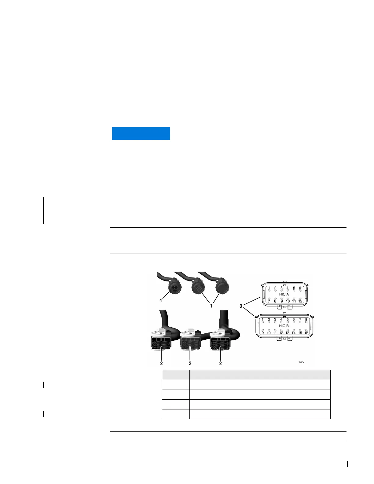
Graphic Connector
Fig. 9
The wiring harness must not be shortened or modified.
Part Function
1 FUSE BOX X1 (LANE A), X2 (LANE B)
2 ECU connector A1, A2, B
3 Harness Interface Connector A, B
4 FUSE BOX X3

 Loading...


