d05783.fm
INSTALLATION MANUAL
BRP-Powertrain
Effectivity: 912 i Series
Edition 1/Rev. 2
72-00-00
Page 8
January 01/2014
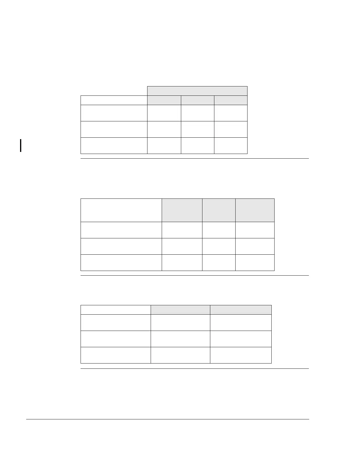
2.2) Installation dimensions
Standard engi-
ne version
See Fig. 2 to Fig. 4.
NOTE: All dimensions from zero reference point (P).
2.3) Centre of gravity of engine and standard accessories
See Fig. 2 to Fig. 4.
NOTE: All dimensions from zero reference point (P).
2.4) Moments of inertia
See Fig. 2 to Fig. 4.
Standard engine version
Pos. (+) Neg. (-) Total
Max. dimension along x-
axis (mm)
8.5
(0.33 in.)
-656.6
(-25.85 in.)
665.1
(26.19 in.)
Max. dimension along y-
axis (mm)
288
(11.34 in.)
-288
(-11.34 in.)
576
(22.68 in.)
Max. dimension along z-
axis (mm)
247
(9.73 in.)
-311
(-12.24 in.)
531
(20.91 in.)
Standard en-
gine version
3
External
alternator
Hydraulic
governor
Centre of gravity on x-axis
(mm)
-327
(-12.87 in.)
-100
(-3.94 in.)
-276
(-10.87 in.)
Centre of gravity on y-axis
(mm)
-9 (-0.35 in.) 139
(5.47 in.)
0
Centre of gravity on z-axis
(mm)
-102
(-4.02 in.)
6 (0.24 in.) 56 (2.20 in.)
Engine version 2 Engine version 3
Moment of inertia around
axis x1-x1 (kg cm
2
)
20470 (48.576 lb ft
2
) 21210 (50.332 lb ft
2
)
Moment of inertia around
axis y1-y1 (kg cm
2
)
24560 (58.282 lb ft
2
) 25450 (60.394 lb ft
2
)
Moment of inertia around
axis z1-z1 (kg cm
2
)
26520 (62.933 lb ft
2
27480 (65.211 lb ft
2
)

 Loading...


