EasyManuals Logo

Rotax 912 i series Installation Manual

Rotax 912 i series
206 pages
To Next Page IconTo Next Page
To Previous Page IconTo Previous Page
Page #181 background imageLoading...
Page #181 background image
d05398.fm
INSTALLATION MANUAL
BRP-Powertrain
Effectivity: 912 i Series
Edition 1/Rev. 0
79-00-00
Page 13
January 01/2012
Connections
2.2) Oil tank
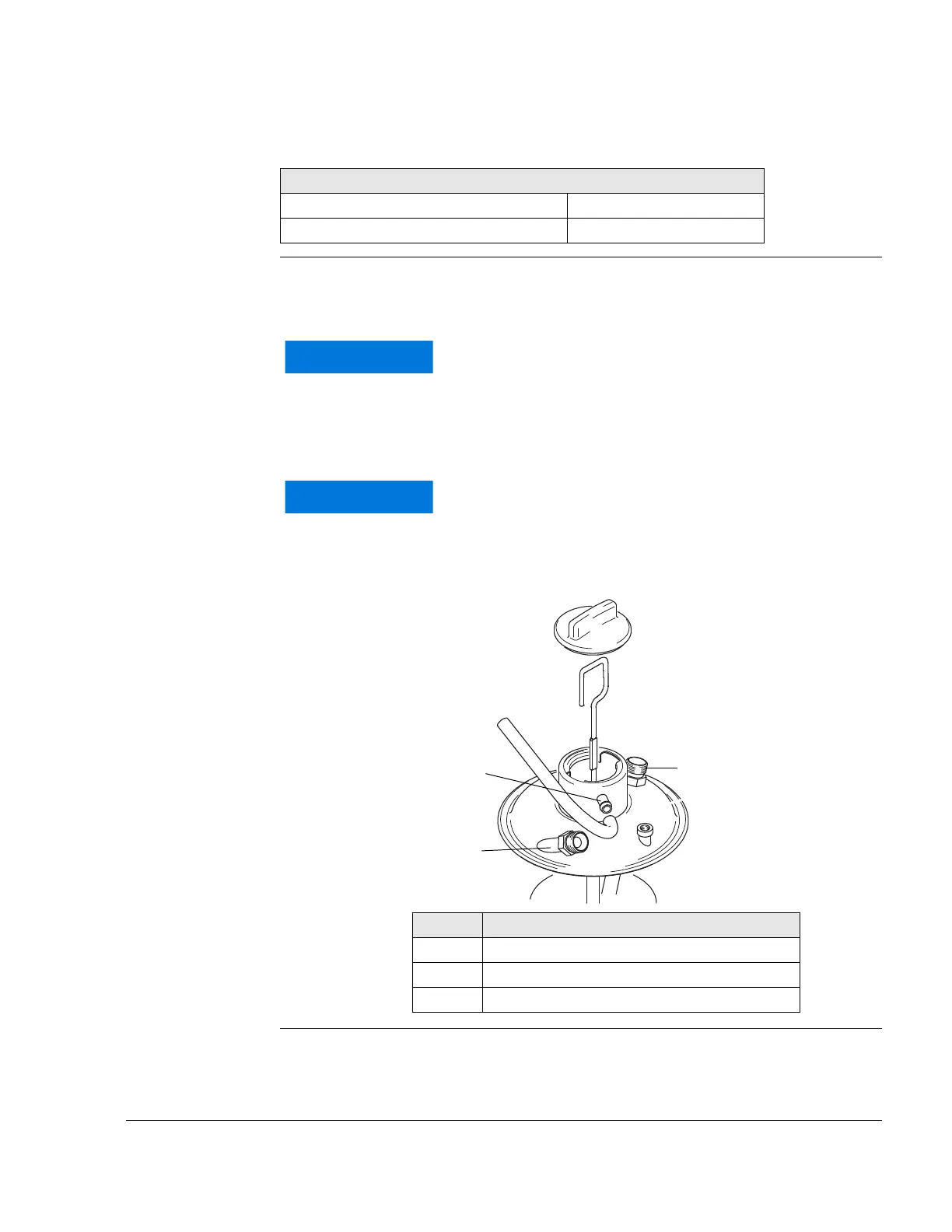
Connections See Fig. 8 and Fig. 9.
NOTE: Optional extra:
Nipple either straight or with 90° elbow. Metric M18x1.5 or
UNF 3/4-16 thread.
Connections for oil circuit (engine)
Graphic
Fig. 8
Screw connection (optional)
Thread 3/4-16 UNF/M16x1.5
Tightening torque of oil return line 25 Nm (18.44 ft.lb.)
WARNUNG
NOTICE
Only use the oil tank provided in the scope of deliv-
ery, as its design has changed compared with older
tanks.
WARNUNG
NOTICE
Check what type of thread or connection there is on
the supplied oil tank.
Part Function
1 Oil feed line
2 Oil outlet
3 Purging nipple
IN
O
U
T
2
1
3

Table of Contents

Other manuals for Rotax 912 i series

Questions and Answers:

Question and Answer IconNeed help?

Do you have a question about the Rotax 912 i series and is the answer not in the manual?

Rotax 912 i series Specifications

General IconGeneral
Number of Cylinders4
Max Power100 hp (73.5 kW)
Max Power Output RPM5800 rpm
Ignition SystemDual electronic ignition
Oil SystemDry sump, forced lubrication with separate oil tank
Reduction Gear Ratio2.43:1
TBO2000 hours
Engine Type4-stroke, horizontally opposed
Displacement1352 cm³
Bore x Stroke84 mm x 61 mm
Max Torque128 Nm
Fuel TypeAvgas 100LL or unleaded automotive gasoline
Fuel SystemElectronic fuel injection
Cooling SystemLiquid/air-cooled

Related product manuals