d05398.fm
INSTALLATION MANUAL
BRP-Powertrain
Effectivity: 912 i Series
Edition 1/Rev. 0
79-00-00
Page 12
January 01/2012
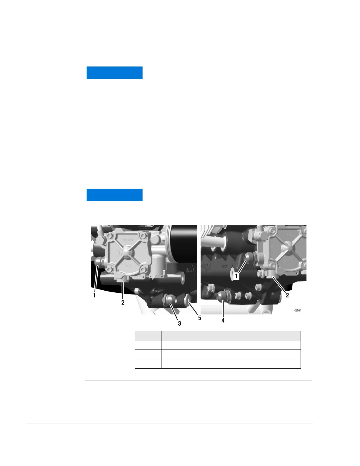
Oil return
See Fig. 7.
Select the appropriate connection for the oil return line according to the
propeller configuration and oil system layout.
- Position 4, 5 for tractor arrangement
- Position 3 for pusher arrangement
Graphic Connections
Fig. 7
The engine design is for a conventional, non-aerobat-
ic, tractor or pusher configuration with the oil return
port in the optimum position. Assuming these points
are taken into consideration, the engine will be prop-
erly lubricated in all flight profiles. Aircraft that are not
conventional (e.g. airships, gyrocopters, dive brake
equipped aircraft, etc.) that require engine load at
steep inclination angles may have special lubrication
requirements.
Check that the connections for the oil feed and return
lines are correct.
Part Function
1 or 2 Screw socket (oil feed line) from oil tank or oil cooler
3 Screw socket (oil return line) for pusher arrangement
4 or 5 Screw socket (oil return line) for tractor arrangement

 Loading...


