d05781.fm
INSTALLATION MANUAL
BRP-Powertrain
Effectivity: 912 i Series
Edition 1/Rev. 2
24-00-00
Page 23
January 01/2014
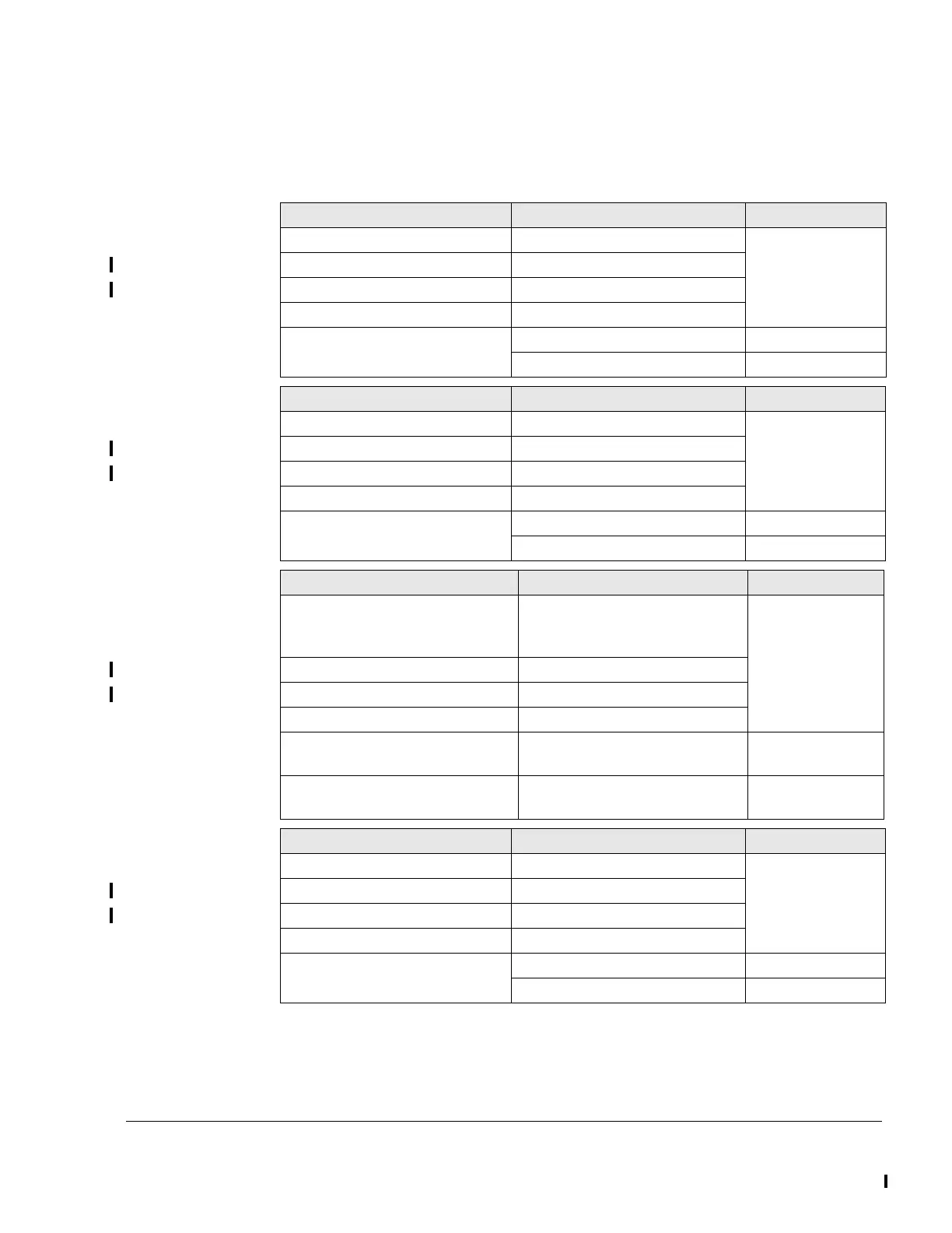
5.2) Switch and warning lamp requirements
Requirements See following table.
LANE SELECT SWITCH A Requirement Connector/slot
Switch type Toggle-SPST HIC A
Nominal voltage 28 VDC
Nominal current 7.5 A
Number of poles 1-pole
Designation on wiring harness LANE_SEL_SW_A_1 1
LANE_SEL_SW_A_2 7
LANE SELECT SWITCH B Requirement Connector/slot
Switch type Toggle-SPST HIC B
Nominal voltage 28 VDC
Nominal current 7.5 A
Number of poles 1-pole
Designation on wiring harness LANE_SEL_SW_B_1 1
LANE_SEL_SW_B_2 9
BACKUP BATTERY SWITCH Requirement Connector/slot
Switch type Toggle (but with mechanical in-
terlock to prevent switch on du-
ring standard operation).
FUSE BOX
Battery (+)
Nominal voltage 28 VDC
Nominal current 20 A
Number of poles 2-pole
Designation on wiring harness Not connected to the wiring har-
ness.
FUSE BOX Must be installed by the aircraft
manufacturer.
FUEL PUMP SWITCH 1 Requirement Connector/slot
Switch type Toggle-SPST HIC A
Nominal voltage 28 VDC
Nominal current 10 A
Number of poles 1-pole
Designation on wiring harness SIG_FUEL_PUMP_1 3
GND_FUEL_PUMP_1 9

 Loading...


