EasyManuals Logo

Rotax 912 i series Installation Manual

Rotax 912 i series
206 pages
To Next Page IconTo Next Page
To Previous Page IconTo Previous Page
Page #39 background imageLoading...
Page #39 background image
d05165.fm
INSTALLATION MANUAL
BRP-Powertrain
Effectivity: 912 i Series
Edition 1/Rev. 0
10-10-00
Page 9
January 01/2012
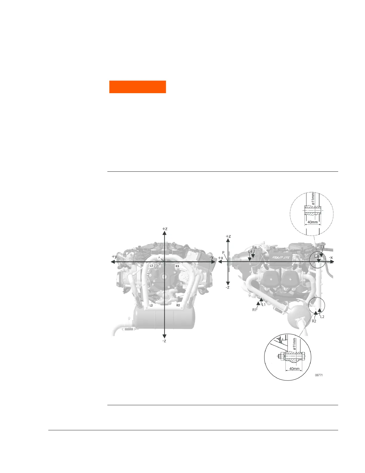
2.3) Definition of attachment points
General note See Fig. 5.
Graphic Attachment points
Fig. 5
WARNUNG
WARNING
Non-compliance can result in serious injuries or
death!
The aircraft or fuselage manufacturer must design the
engine suspension so that it can safely carry the max-
imum occurring operational loads without exceeding
the max. allowable forces and bending moments on
the engine housing and attachment points.
Tighten all engine suspension screws as specified by
the aircraft manufacturer.

Table of Contents

Other manuals for Rotax 912 i series

Questions and Answers:

Question and Answer IconNeed help?

Do you have a question about the Rotax 912 i series and is the answer not in the manual?

Rotax 912 i series Specifications

General IconGeneral
Number of Cylinders4
Max Power100 hp (73.5 kW)
Max Power Output RPM5800 rpm
Ignition SystemDual electronic ignition
Oil SystemDry sump, forced lubrication with separate oil tank
Reduction Gear Ratio2.43:1
TBO2000 hours
Engine Type4-stroke, horizontally opposed
Displacement1352 cm³
Bore x Stroke84 mm x 61 mm
Max Torque128 Nm
Fuel TypeAvgas 100LL or unleaded automotive gasoline
Fuel SystemElectronic fuel injection
Cooling SystemLiquid/air-cooled

Related product manuals