d05781.fm
INSTALLATION MANUAL
BRP-Powertrain
Effectivity: 912 i Series
Edition 1/Rev. 2
24-00-00
Page 16
January 01/2014
NOTES
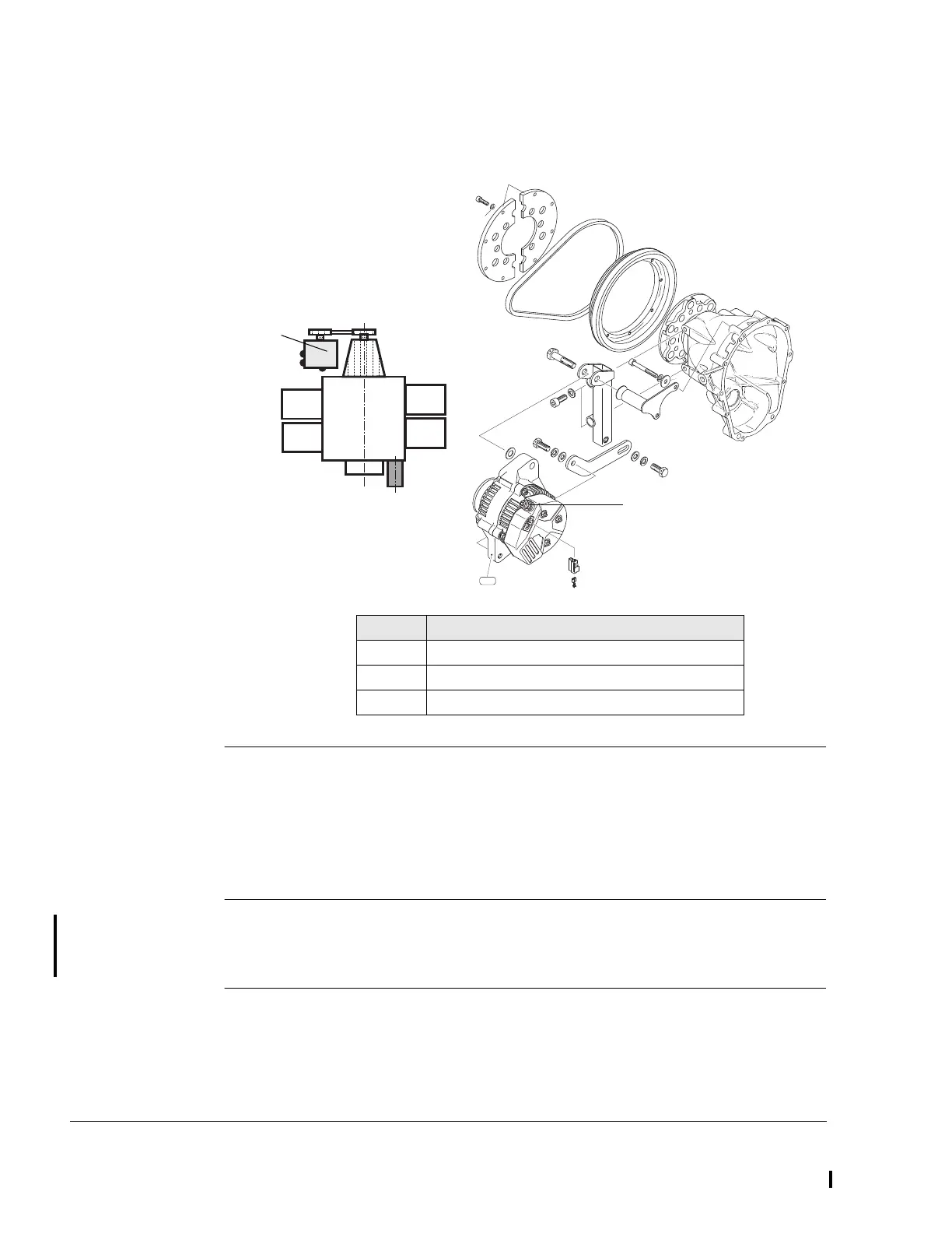
Graphic External alternator
Fig. 7 03199,02764,00547
4.2.1) Requirements for correct operation of the integrated rectifier
regulator
Fuse The rectifier regulator must be protected by a slow blowing fuse or circuit
breaker. Fuse or circuit breaker rating must be determined by load, wire
size and length.
Load distribution Due to slightly different output voltages of the regulators (alternator and
regulator A/B of fuse box) the power is drawn by the generator with the
higher output voltage at low load.
Part Function
1 External alternator
2 Positive terminal
3 Control wiring
IG
L
B
Cyl. 1
Cyl. 3
Cyl. 2
Cyl. 4

 Loading...


