RKHBH/X008AA
Indoor unit for air to water heat pump system
4PW50203-1A
Installation manual
7
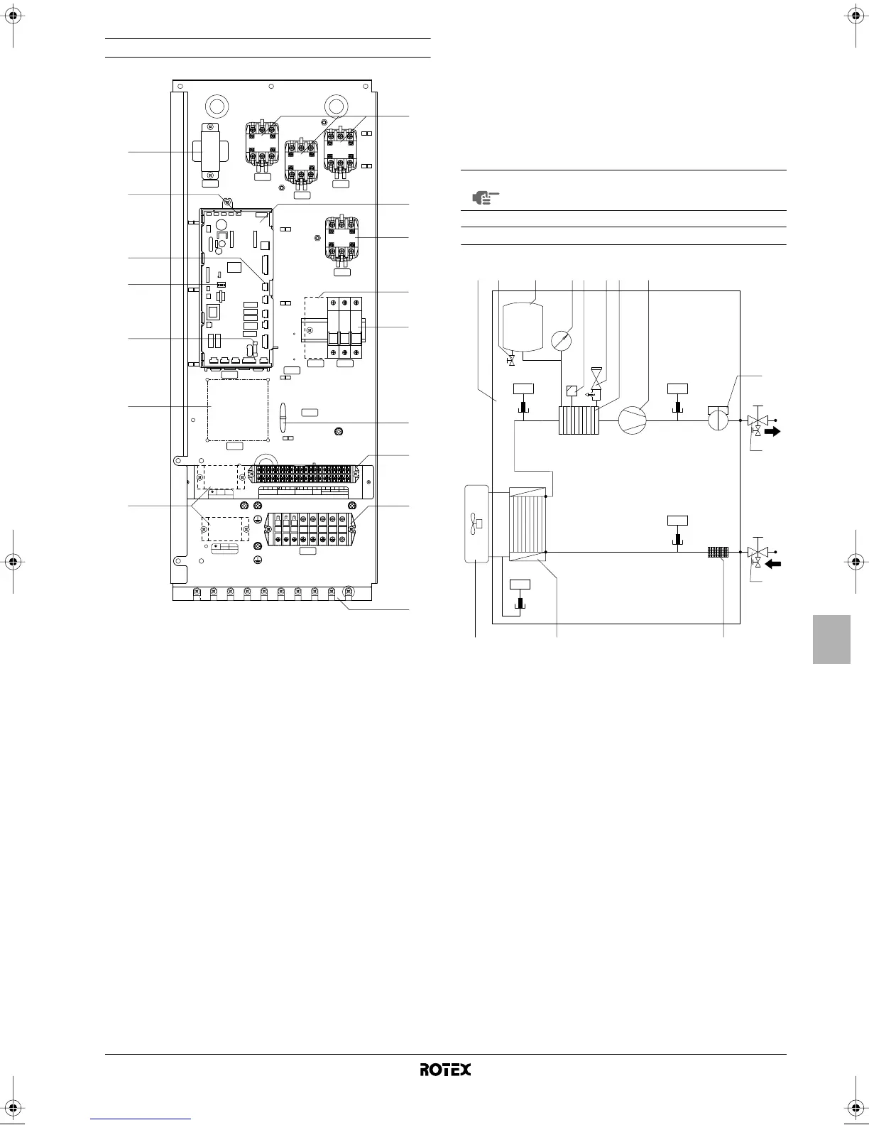
Switch box main components
1. Backup heater contactors K1M, K2M and K5M
2. Main PCB
The main PCB (Printed Circuit Board) controls the functioning of
the unit.
3. Booster heater contactor K3M (only for installations with
domestic hot water tank)
4. Booster heater circuit breaker F2B (only for installations with
domestic hot water tank)
The circuit breaker protects the booster heater in the domestic
hot
water tank against overload or short circuit.
5. Backup heater circuit breaker F1B
The circuit breaker protects the backup heater electrical circuit
against overload or short circuit.
6. Ter minal blocks
The terminal blocks allow easy connection of field wiring.
7. Cable tie mountings
The cable tie mountings allow to fix the field wiring with cable
ties to the switch box to ensure strain relief.
8. Ter minal blocks X3M, X4M (only for installations with domestic
hot water tank)
9. PCB fuse FU1
10. DIP switch SS2
The DIP switch SS2 provides 4 toggle switches to configure
certain installation parameters. See "DIP switch settings
overview" on page 15.
11. X13A socket
The X13A socket receives the K3M connector (only for
installations with domestic hot water tank).
12. X9A socket
The X9A socket receives the thermistor connector (only for
installations with domestic hot water tank).
13. In line fuse FU2
14. Transformer TR1
15. A4P
Remote alarm address card (only for installations with remote
alarm kit).
Functional diagram
7
2-way valve
TR1
TR1
14
12
11
10
9
15
8
1
2
3
4
5
6
6
7
X9A
X13A
SS2
K1M
K2M
K5M
K3M
F2B
F1B
X3M
X4M
A4P
A1P
K1M
K2M
K5M
K3M
F2B
F1B
X1M
A4P
A1P
12
X4M
X2M
X3M (230V)
L1 L2
LN
thermostat 3-way valve
thermal
fuse
OPTIONAL
Q2L
8910111213 14 15 16 17 181234 56
SS2
SS1
on
off
on
FU1
13
FU2
OPTION EKHW
OPTION EKHW
OPTION EKHW
OPTION EKHW
NOTE
The electrical wiring diagram can be found on the
inside of the switch box cover.
1 Outdoor unit 10 Flow switch
2 Indoor unit 11 Shut-off valve water outlet
with drain valve (field
installation)
3 Expansion vessel drain
valve
4 Expansion vessel 12 Shut-off valve water inlet with
drain valve (field installation)
5 Manometer
6 Air purge valve 13 Filter
7 Pressure relief valve 14 Heat exchanger
8 Backup heater vessel
with backup heater
R1T
R2T
R3T
R4T
Temperature sensors
9 Pump
R4T
H
2
O
t >
R3T
t >
R2T
t >
R1T
t >
10
11
12
432 5 9
13141
6 7 8
1D_IM_4PW50203-1A.book Page 7 Thursday, January 29, 2009 10:51 AM
 Loading...