Installation manual
16
RKHBH/X008AA
Indoor unit for air to water heat pump system
4PW50203-1A
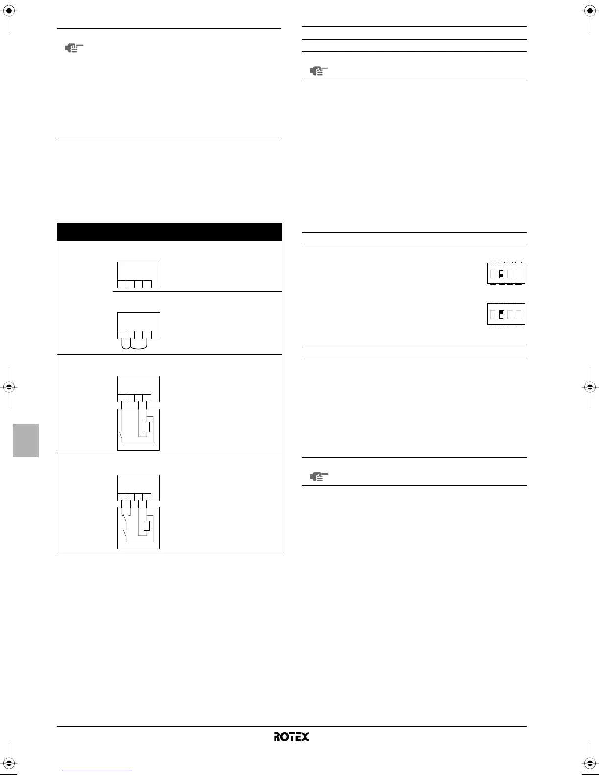
The following table summarizes the required configuration and
thermostat wiring at the terminal block in the switch box. Pump
operation is listed in the third column. The three last columns indicate
whether the following functionality is available on the user interface
(UI) or handled by the thermostat (T):
• space heating or cooling on/off (y)
• heating/cooling changeover (=)
• heating and cooling schedule timers (pr)
Pump operation configuration
Without room thermostat
When no thermostat is connected to the indoor unit, pump operation
will be determined by the leaving water temperature.
To force continuous pump operation when no room thermostat is
connected do the following:
- set toggle switch SS2-3 to ON,
- short-circuit the terminal numbers 1-2-4 on the terminal block
in the switch box.
With room thermostat
When a thermostat is connected to the indoor unit, the pump will
operate continuously whenever there is heating or cooling demand
requested by the thermostat.
Domestic hot water tank installation configuration
Initial start-up at low outdoor ambient temperatures
During initial start-up and when water temperature is low, it is
important that the water is heated gradually. Failure to do so may
result in cracking of concrete floors due to rapid temperature change.
Please contact the responsible cast concrete building contractor for
further details.
To do so, the lowest leaving water set temperature can be decreased
to a value between 15°C and 25°C by adjusting the field setting
[9-01] (heating set point lower limit). Refer to "Field settings" on
page 17.
NOTE
■ When a room thermostat is connected to the
indoor unit, the heating and cooling schedule
timers are never available. Other schedule timers
are not affected. For more information on the
schedule timers, refer to the operation manual.
■ When a room thermostat is connected to the
indoor unit, and the = button or y button is
pressed, the centralised control indicator e will
flash to indicate that the room thermostat has
priority and controls on/off operation and change
over operation.
Thermostat Configuration
Pump
operation
yy
yy
==
==
pp
pp
rr
rr
No thermostat
• SS2-3 = OFF
• wiring: (non)
determined by
leaving water
temperature
(a)
(a) The pump will stop when space heating/cooling is turned off or when the water
reaches the desired water temperature as set on the user interface. With space
heating/cooling turned on, the pump will then run every 5 minutes during 3
minutes to check the water temperature.
UI UI UI
• SS2-3 = ON
• wiring:
on when space
heating or
cooling is on
(y)
UI UI UI
Heating only
thermostat
• SS2-3 = ON
• wiring:
on when
heating
request by
room
thermostat
T——
Thermostat with
heating/cooling
switch
• SS2-3 = ON
• wiring:
on when
heating
request or
cooling request
by room
thermostat
TT—
th =
Thermostat contact
C =
Cooling contact
H =
Heating contact
L, N =
230 V AC
X2M
H CLN
1 234
X2M
H CLN
1 234
X2M
HC
H
th
C
LN
1 234
NOTE
To set the pump speed, refer to "Setting the pump
speed" on page 17.
■ When no domestic hot water tank is
installed, toggle switch SS2-2 should be set to
OFF (default).
■ When a domestic hot water tank is installed,
toggle switch SS2-2 should be set to ON.
NOTE
Heating between 15°C and 25°C is performed by the
backup heater only.
4321
ONOFF
4321
ONOFF
1D_IM_4PW50203-1A.book Page 16 Thursday, January 29, 2009 10:51 AM
 Loading...