Installation & Maintenance Instructions
12
5. Installation & Setup
Relay1:
N/O
N/C
Common
Relay2:
N/O
N/C
Common
POS
I
T
REMOTE
Note: Current Position Transmitter (CPT )isloop powered.
CPT Feedback-
CPT Feedback+
Demand -
Demand +
MainsInput
LN
Neutral
Live
(Earth stud
located behind)
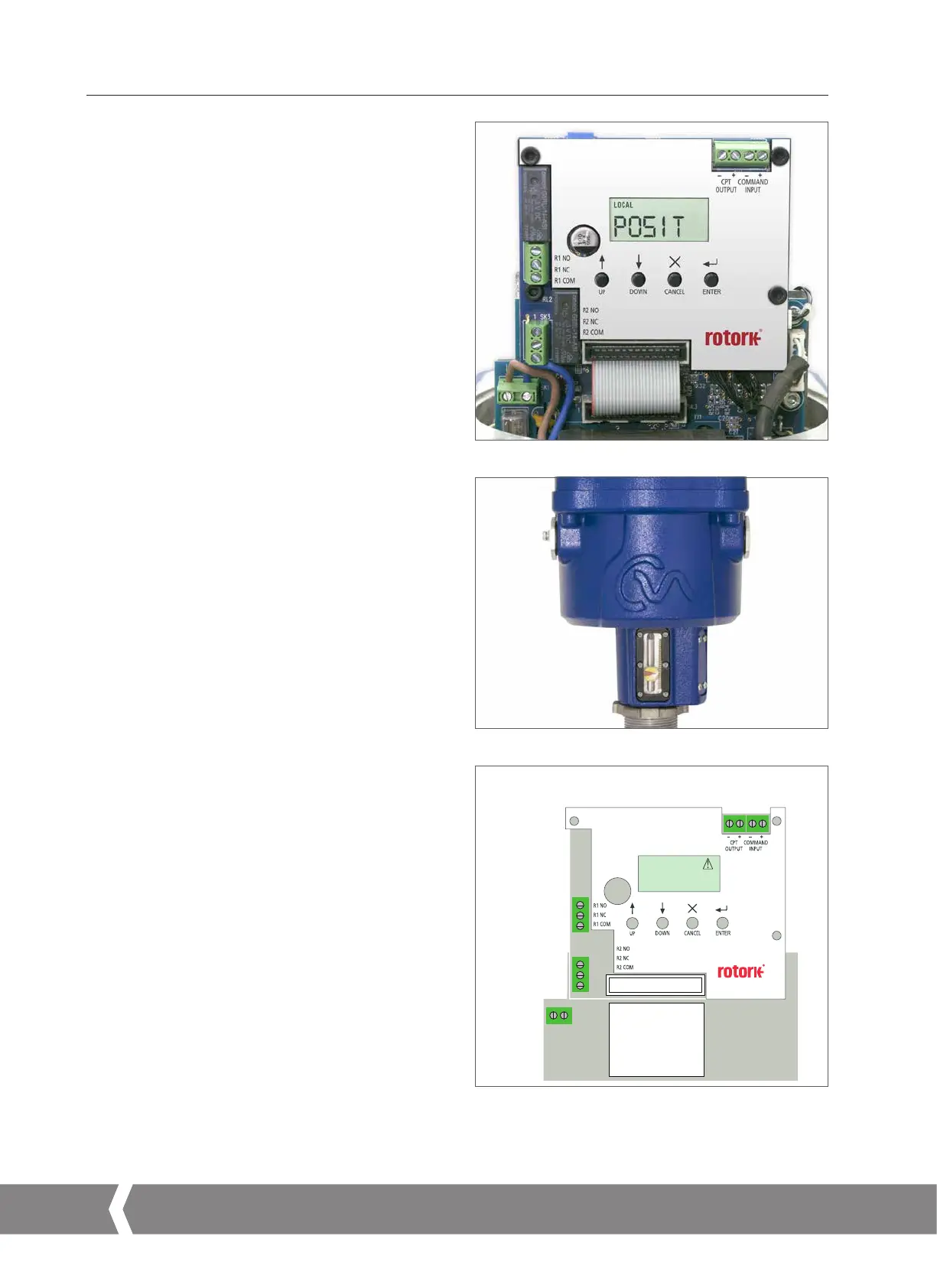
5.2.2 Standard Actuator
The standard actuator is supplied without local control knobs
or external display. Removal of top cover assembly is required
to adjust configuration parameters and facilitate connection
of power and field wiring.
5.2.3 Local Indicator
CML has one indicator as standard. All variants can be fitted
with optional extended cover with local display window.
5.2.4 Main Printed Circuit Board (PCB) Layout
Fig 5.2
Fig 5.3
Fig 5.4 Main PCB
A4US
US
A4
US A4
US
A4
 Loading...

