Installation & Maintenance Instructions
20
7. Mounting the Actuator – CMQ Quarter-Turn Actuators Only
Stop Bolt Adjustment
It is recommended that stop bolt adjustment be carried out
by the valvemaker/supplier before the valve is fitted in to the
pipework.
Once installed the valvemaker/supplier should be consulted
before stop bolt re-adjustment is carried out. After setting or
adjustment of stop bolts the actuator limits must be reset.
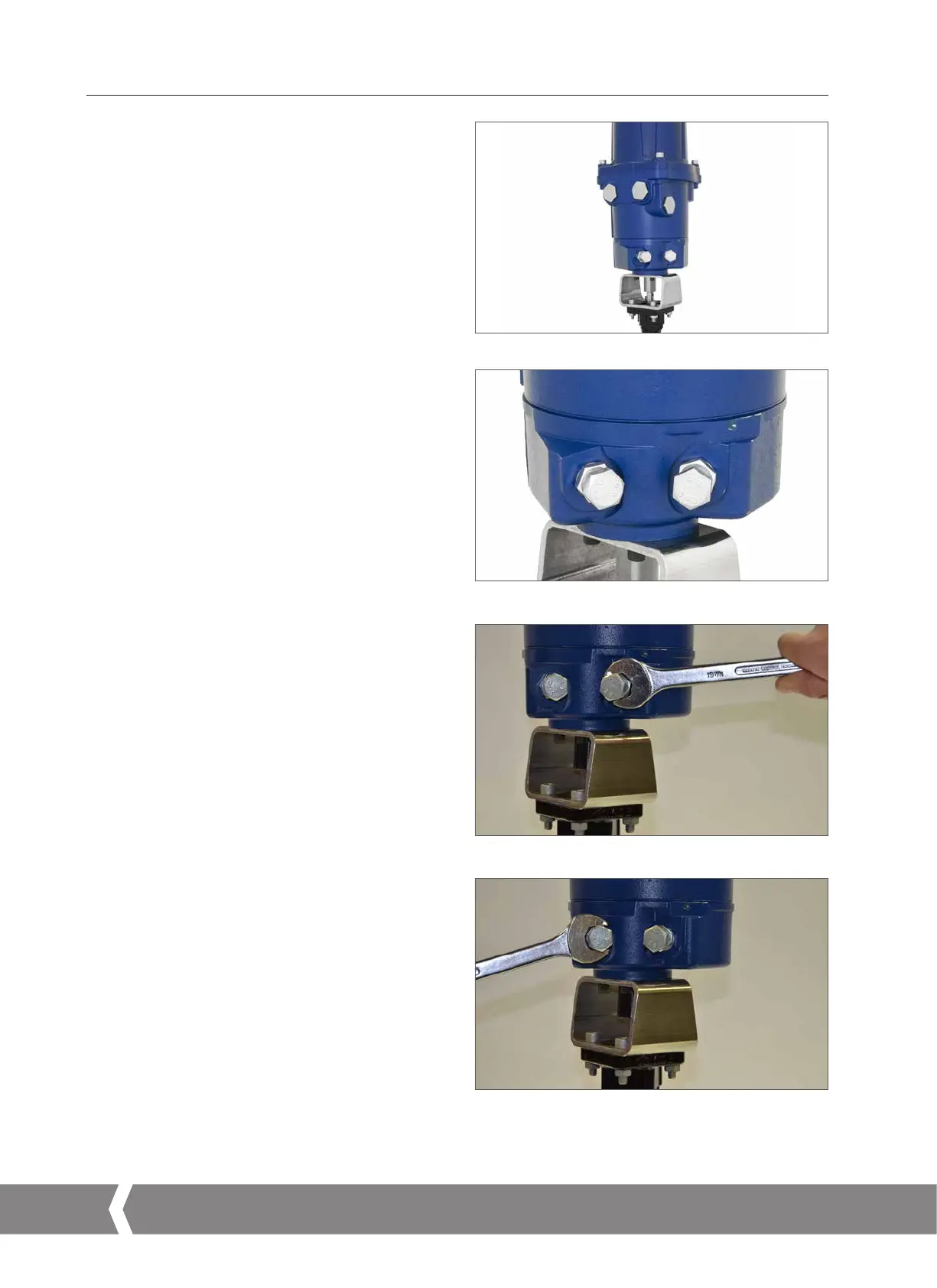
The CMA stop bolts are located on the lower body assembly.
The stop bolt adjustment allows +/- 5º variation of travel at
each end position. Screwing bolts in reduces the range of
movement, out increases range of movement.
For clockwise closing valves the right hand bolt is the closed
stop as shown in Fig 7.8. The left hand bolt is the open stop.
Stop bolts are factory set to give a nominal travel of 90°.
Adjustment for Non Seating Valve Types
For closed and open stop position adjustment. Undo stop
bolt locknut. Move actuator and valve to the required
stopping position (it may be necessary to unscrew stop bolt
to allow more travel). Screw stop bolt in until a stop is felt.
Tighten stop bolt lock nut.
Adjustment for Seating Valve Types
Undo stop bolt locknut. Move actuator and valve to the
required stopping position (it may be necessary to unscrew
stop bolt to allow more travel). Screw stop bolt in until a stop
is felt and then back off by 1 to 3 turns. Tighten stop bolt
lock nut.
Go to page 23 for electrical installation and basic setup
instructions.
Fig 7.7
Fig 7.8
Fig 7.9
Fig 7.10
A4US
US
A4
US A4
US
A4
 Loading...


