pag. 13
ST2 User’s Manual
Introduction
and then press the
key to access the “SYSTEM MENU MOTOR” menu:
Referring to fi g. 1.0, press the
key to select “DiSEqC MOTOR”
“DiSEqC MOTOR” (menu to drive motorized antennas):
continue: CONFIGURATION MENU
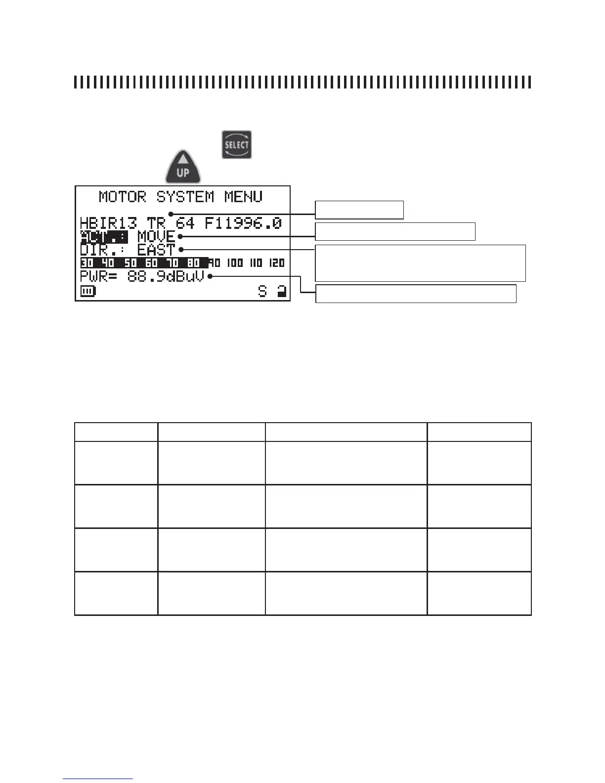
The fi rst display line shows the satellite to which we want to aim the motorized dish (i.e. Hot Bird 13°
E). The wanted satellite may be selected using the PLAN [3] key (see par. 2.0).
The motor action is called “ACT”. Depending on the verb selected in this fi eld, using the UP and
DOWN keys, sub fi elds will be shown (see table below) that will allow the completion of the desired
action. Once the wanted action has been properly confi gured, move to the Next line of the display
using the SELECT key and change its status using the UP and DOWN keys (see ACT enabling
column in the table below).
ACT ACT sub fi elds Description ACT enabling
MOVE none allows the meter movement
towards the wanted direction
EAST or WEST
DIR:
• EAST
• WEST
GOTO from POS 1 to
POS 99
selects one of the 99 motor pre-
memorized positions
APPLY?
(move to the se-
lected position)
STORE from POS 1 to
POS 99
memorizes the current motor po-
sition in one of the 99 possible
memory locations.
STORE?
(stores the current
motor position)
RESET none removes any eventual rotational
preset EAST or WEST motor
movements limits.
APPLY?
(removes rotation
blockages)
Selected satellite
Motor Action (see table below)
Motor action enabling (see table below). The infor-
mation on this line depends on the selection made
in the “ACT” fi eld.
received signal Power measurement
During the alignment phase, the displayed measurements is only the average digital power measurement .
Once the satellite has been recognized, the meter will show the Noise Margin measurement and the quality
analysis (PASS, MARGINAL, FAIL) as well as the Service handler data.
NOTE
Press any key to exit the “DiSEqC MOTOR” function.