12
4-20mA sensors
Use third party 4-20mA sensors as per specication on page 8. Connect the 4-20mA sensors at the back of the unit marked “4-20mA
Sensors” to any one of three available inputs. Extend the 4-20mA sensors using standard CAT-5 cable to a maximum distance as
specied by the sensor manufacturer. Tie the cable to the cable support at the back of the unit using the tie wraps provided. The TM3
Monitoring Unit implements a 100 sense resistor to which the 4-20mA sensor connects. At the back of the unit two 12V (200mA) power
supply and one 18V (50mA) power supply outputs are available for sensor power supply. Ensure that the 4-20mA sensor does not
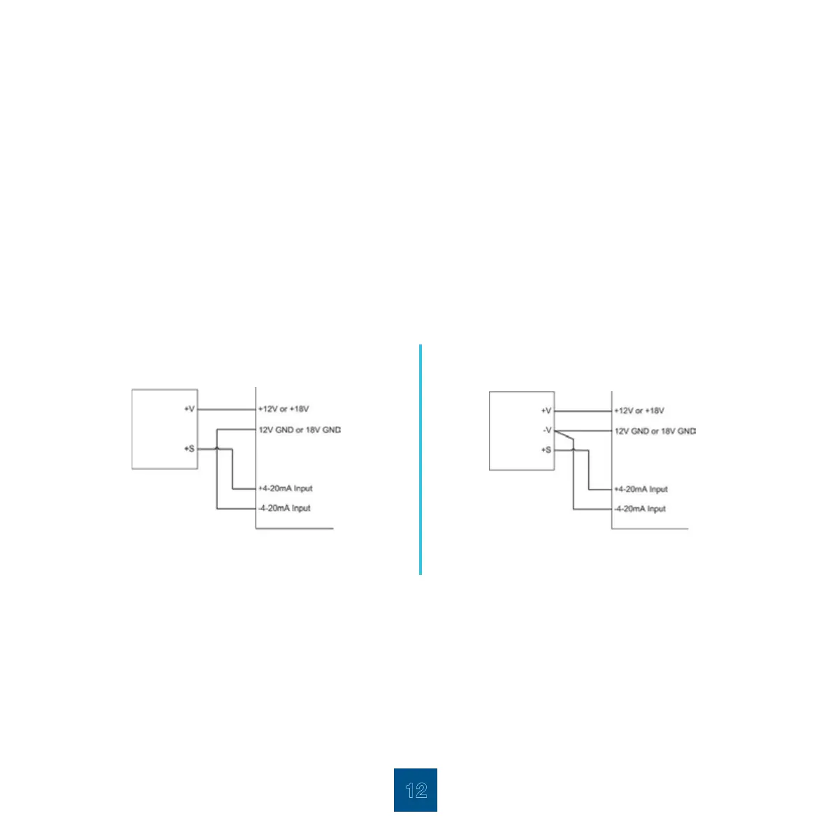
overload the power supply. Two wire and three wire sensor connections are shown below. 4-20ma sensors that are available: Humidity,
Temperature, Amperage.
two wire sensor connection three wire sensor connection
relay connection
Connect the cable that is connected to external device to the back of the unit to either one of the two relays. Common/Normally Open
or Common/Normally Closed contacts can be used. Relays can be Energised/De-energised by either going into the Dry Contacts Alarms
Conguration Page and selecting 0 = De-energise or 1 = Energise or by sending an SMS command to the TM3 Unit.
+ V= power in
+ S= signal output
TM3 unit4-20mA sensors
+ V= power in
- V= power in GND
+ S= signal output
4-20mA sensors TM3 unit