1919
configuration
This section describes generic conguration procedures which are required to congure a unit for a specic operational installation.
Conguring a unit entails the following basic steps by selecting the appropriate TABS on the web interface TAB bar:
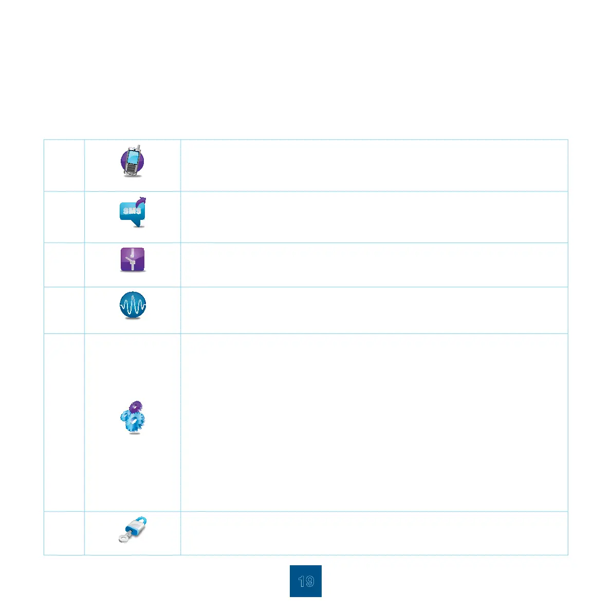
Step 1:
Contacts
Set up your contacts in the Contacts Conguration Page. Here you specify all the numbers and
names to which SMSs have to be sent.
Step 2:
Alarm Proles
Set up the alarm proles in the Alarm Prole Conguration Page. This species which alarms have
to be sent to which contacts.
Step 3:
Dry Contact Alarms
Set up the dry contact alarms in the Dry Contact Alarm Conguration Page. Alarm descriptions,
active levels and Enable/Disable settings are done on this page.
Step 4:
Analogue Alarms
Set up the analogue alarms in the Analogue Alarms Conguration Page. Analogue alarms include
the temperature, ood, 4-20mA sensors and TM power supply. Transmission selection, Alarm
descriptions, and Enable/Disable settings are done on this page.
Step 5:
Conguration Page
Miscellaneous conguration is performed in the Conguration Page and include the following:
n 4-20mA Sensors where threshold levels are congured
n GSM (refer to Initial Conguration GSM Conguration on page 15)
n Ethernet/Internet (refer to Initial Conguration Ethernet/Internet Conguration on page 17)
n Self Test where a weekly self test is scheduled
n Temperature Sensors, where the temperature sensor sampling period, hysteresis levels and
threshold levels are congured
n Disabled Alarms, where a daily disabled alarms report is scheduled
n Uncleared Alarms, where a daily uncleared alarms report is scheduled
n General, the Site identication name is specied as well as the dry contact alarm delay time.
The software version of the unit is displayed in this page
n Camera. A network enabled camera can be viewed on the web – interface. In this page the
camera IP Address is congured. Change the administrator and user passwords in this page
n SNMP conguration is done on this page where access parameters are entered
Step 6:
Security
Change the administrator and user passwords and congure the auto logout on this page.