© Safe Fleet | 2020 | All rights reserved | Part #: 700-1213 R1
DH4C Installation Guide
p. 29
DH4C Basic Conguration
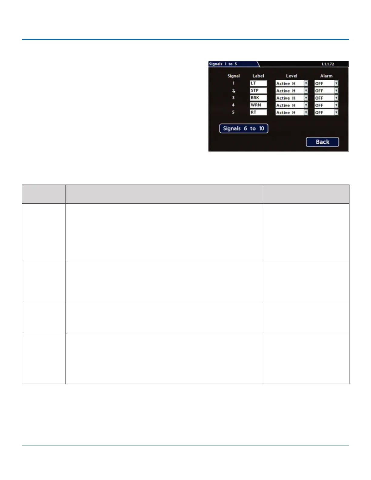
To Congure Signals:
1. Select Alarm/Signal Signals to open the tab.
2. Congure signals as required.
Each signal displays its status (label) when active, and can
also trigger an Alarm. For details, see Menu Options, below.
3. Click Back to save settings, then click Back again to return to
the Conguration menu.
ITEM DESCRIPTION VALUE [DEFAULT]
Signal Signals 1 through 5 are hardwired inputs, received through the signal
harness (LT/left turn signal - black wire, STP/stop - green wire, BRK/
brake - red wire, WRN/warning lights - brown wire, and RT/right turn
signal - white wire). When these triggers are active, they generate
signals and display associated labels during video playback.
Signals 6 through 10 can be user-dened.
n/a
Label You can edit the on-screen display text label (maximum 3 characters)
to describe each signal as desired.
For instructions on using the mouse to enter data, see DH4C Operation:
Using On-screen Keyboards.
Labels 1 through 5: [LT],
[STP], [BRK], [WRN], [RT].
Labels 6 through 10: [S06],
[S07], [S08], [S09], [S10]
Level Control how the signal senses activation: choose Active H (high) if the
circuit rests at 0 VDC and goes to 12 VDC when active; choose Active L
(low) if the circuit rests at 12 VDC and drops to 0 when active.
[Active H], Active L
Alarm Select the alarm number if the signal is also used to trigger an alarm.
The alarm's input must also be set up in the Alarms menu.
Note: assigning alarms to the default signals 1 through 5 is generally
not recommended, since these would be continually triggered by
normal vehicle operation.
[OFF], ALM1, ALM2, ALM3,
ALM4
Menu Options