© Safe Fleet | 2020 | All rights reserved | Part #: 700-1213 R1
DH4C Installation Guide
p. 40
DH4C Advanced Conguration
G-Sensor
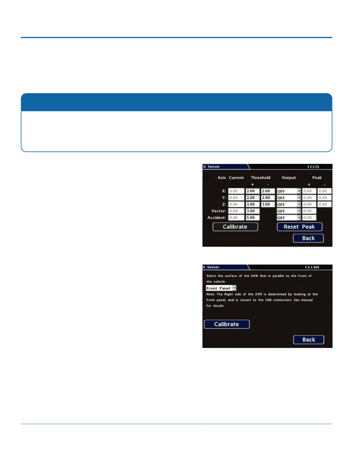
Conguring G-Sensor Options
i. Ensure all DVR surfaces are parallel to the front of the
vehicle and perpendicular to the oor.
ii. Click Calibrate.
3. In the G Sensor calibration menu, from the drop down eld,
select the DVR surface that is parallel to the front of the
vehicle.
4. Click Calibrate for the G Sensor to set the X/Y/Z axis planes,
based on the mounting surface selection. When the process
is done, a "Calibration Complete" message appears.
5. If required, adjust G Sensor settings. For details, see Menu
Options, below.
6. Click Back to save settings, then click Back again to return to
the Conguration menu.
Calibration
The G-Sensor must be calibrated when initially installed or if the unit is relocated, and the procedure must be per-
formed on the vehicle (i.e. not by connecting to the DVR from a remote location).
G-Sensor settings can be adjusted to t specic requirements. Note that if thresholds are set too low and alarms are
enabled, many alarms may be generated. Details are provided below.
To congure G-Sensor settings:
1. Select Alarm/Signal G-Sensor to open the tab.
2. If this is a new system installation, or the DVR has been
relocated, perform the following Calibration procedure: