EB 5824-2 EN 3-1
Design and principle of operation
3 Design and principle of oper-
ation
A stepper motor allows for supply by fre-
quency-independent voltages. The force of
the motor is transmitted to the actuator stem
(3) via gear and crank disk. When the actu-
ator stem extends, the actuator piston (3)
pushes against the valve's plug stem.
When the actuator stem retracts (force-lock-
ing attachment), the plug stem follows the
movement of the actuator stem as a result of
the return spring in the valve.
Whentheactuatorstemretracts(form-tat-
tachment), the plug stem is connected to the
actuator stem and follows its movement.
The positioner ensures a predetermined as-
signment of the valve position to the input
signal.Forpositionfeedback,a0to10V
signal can be picked off at terminals 32 and
33.
The characteristic and the input and output
signal settings can be changed using the
TROVIS-VIEW software (uEB6661).
Type 5824 without fail-safe action
The actuator without fail-safe action has a
handwheel (2) used to manually position the
valve. Travel and direction of action can be
read off the travel indication scale (9).
0
6
12
15
15
12
6
0
4
5 6
3
ON
OFF
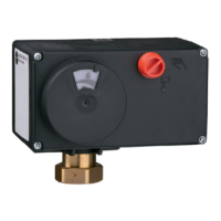
1 Housing
1.1 Front cover
1.2 Cable entry
2 Handwheel(Type5824only)
2.1 Actuating shaft
3 Actuator stem with actuator
piston
4 Coupling nut
5 Cam disk
6 Limit contact
7.1 Adjuster for limit contact
(bottom contact cam)
7.2 Adjuster for limit contact
(top contact cam)
8 Springassembly(Type5825
only)
9 Travel indication scale
9.1 Follower pin
10 Torque-dependent limit switch
Do not open the back
housing cover.
Fig.3-1: Type5824/5825 Actuator (front cover open), with force-locking attachment to the valve