EB 5824-2 EN 5-1
Installation
5 Installation
5.1 Installation conditions
Work position
If not described otherwise in the valve docu-
mentation, the work position for the control
valve is the front view looking onto the oper-
ating controls.
Mounting orientation
The control valve can be installed in the
pipelineinanydesiredposition.However,a
suspended mounting position of the actuator
isnotpermissible(seeFig.5-1).
0...90°
...90°
Fig.5-1: Mounting position
The degree of protection IP54 can only be
achieved up to device index .03 when the
actuator is installed in the upright position.
See the last two gures of the conguration
ID written on the nameplate for the device
index.
5.2 Preparation for installation
Before installation, make sure the following
conditionsaremet:
− The actuator is not damaged.
Proceedasfollows:
Lay out the necessary material and tools to
have them ready during installation work.
Cover screws
The actuator housing cover is fastened using
TORX PLUS
®
screws, size 10IP.
Î To loosen and tighten the screws, the
followingscrewdriverscanbeused:
− TORX
®
T10
− TORX PLUS
®
10IP
− Flat-bladescrewdriverwith0.8mm
bladethicknessand4.0mmbladewidth
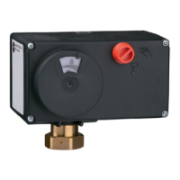
5.3 Aligning the travel indica-
tion scale
The travel indication scale has two opposed
scales. Which scale is to be used depends
on the valve version. In the delivered state,
the scale alignment applies to globe valves
and three-way diverting valves. The align-
Note