5-2 EB 5824-2 EN
Installation
ment needs to be changed when a three-
way mixing valve is used.
0
0
6
6
12
15
12
15
0
15
12
6
Holefordrivingpin
with three-way mixing
valve
Driving pin in position 0,
location of scale with globe or three-way
diverting valves (delivered state)
Fig.5-2: Travel indication scale
Globeandthree-waydivertingvalves:
the driving pin is in position 0 (delivered
state).
Three-waymixingvalve:
change the alignment of the scale.
Î Carefully open the front cover.
We recommend screwing the bottom screws
of the open housing front cover into the top
holes of the housing.
Î Remove scale, turn it and replace it so
that the pin is positioned over the appro-
priate hole (6, 12 or 15) corresponding
totheratedtravel(6,1or15mmtravel).
Î Close front cover.
Tip
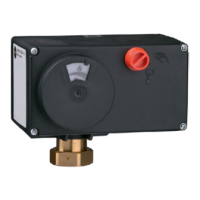
5.4 Mounting the actuator
The actuator is mounted either directly onto
the valve or using a yoke depending on the
valveversionused(seeFig.5-3).
5.4.1 Type5824:force-
locking attachment
1. Turn the handwheel (2) counterclockwise
to retract the actuator stem.
2. Place the actuator on the valve connec-
tion and fasten with the coupling nut (4).
Tightening torque 20Nm
Risk of actuator damage due to unautho-
rized opening of the back housing cover.
Î Do not open the back housing cover.
5.4.2 Type5824:form-t
attachment
1. Place the actuator on the yoke and fasten
with the coupling nut (4).
Tightening torque 20Nm
Place actuator with yoke (15) on the
valve and fasten with the nut (17).
Tightening torque 150Nm
2. Pull plug stem until it reaches the actua-
tor stem or extend actuator stem using
the handwheel (2).
NOTICE
!