EB 5824-2 EN 5-3
Installation
3. Position the clamps of the stem connector
(16) included in the accessories on the
ends of the actuator stem and plug stem
and screw tight.
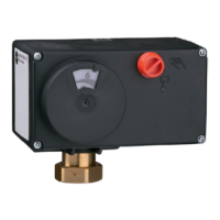
5.4.3 Type5825:force-
locking attachment
Fail-safe action "actuator stem extends"
The actuator stem must be retracted before
the actuator can be mounted onto the valve.
The stem can be retracted either mechanical-
ly or electrically. Both methods are described
below.
Retracting the actuator stem mechanically
1. Unscrewfrontcoverandplacea4mm
Allen key on the red actuating shaft.
2. Retracttheactuatorstem:turnAllenkey
counterclockwise and only as far as the
top end position which is at the point
where the torque-dependent limit switch
isactivated(seeFig.5-4).
Risk of damage to the actuator by turning it
too far.
Î Move the actuator stem only as far as the
top end position.
3. HoldAllenkeyinplaceandfastenvalve
and actuator together using the coupling
nut.
Tightening torque 20Nm
Remove Allen key and carefully refasten
the front cover.
Retracting the actuator stem electrically
1. Unscrew front cover.
2. Perform electrical wiring according to
section5.6andcarefullyrefastenthe
front cover.
3. Retractactuatorstem:
− Switch on the supply voltage and retract
the actuator stem electrically until it
reaches the end position by applying a
signal to the input (see the 'Operation'
section).
4. Fasten valve and actuator together using
the coupling nut.
Tightening torque 20Nm
Fail-safe action "actuator stem retracts"
Î Place the actuator on the valve connec-
tion and fasten with the coupling nut.
Tightening torque 20Nm
5.4.4 Type5825:form-tat-
tachment
Î For fail-safe action “actuator stem re-
tracts” and “actuator stem extends”,
mount actuator as described in sec-
tion5.4.2.
5.5 Installing the control valve
into the pipeline
Î Install the valve into the pipeline accord-
ingthespecicationsinthemounting
and operating instructions of the valve.
NOTICE
!