1.3 Display
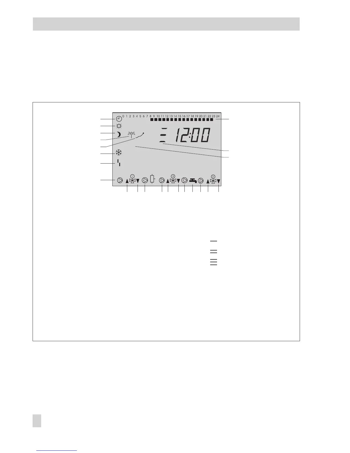
During operation, the display indicates the current time as well as information about the op-
eration of the controller. The times-of-use are represented by black squares below the row of
numbers at the top of the display. Icons indicate the operating status of the controller.
The controller status can be displayed in the operating level (–> section 1.4).
10 EB 5579 EN
Operation
STOP
120
2
3
6
7
8
9
4
5
10 11 12 13 14 15 16 17 18 19
21
22
Fig. 1 · Icons
1 Automatic operation
2 Day mode
(rated operation)
3 Night mode
(reduced operation)
4 Vacation mode
5 Public holiday mode
6 Frost protection
7 Operational fault
8 Circulation pump
UP1*
9 Valve Rk1: OPEN
10 Valve Rk1: CLOSED
11 Storage tank charging
pump SLP
12 Output UP3, bA9*
13 Valve Rk3: OPEN
14 Valve Rk3: CLOSED
15 Circulation pump UP5*
16 DHW demand
17 Circulation pump UP2*
18 Valve Rk2: OPEN
19 Valve Rk2: CLOSED
20 Time-of-use
21 Control circuit assignment:
: Heating circuit Rk1
: Heating circuit Rk2
: Heating circuit Rk3
22 Outdoor temperature
dependent control
deactivated
* UP1, UP2, UP3, SLP, UP5, bA9 indicate possible choices for pump selection in manual mode.