Parameters*
WE Parameter level / Range of values
Station address (ST.-NR) 255 PA6 / 1 to 247 with CO6 -> F02 - 1: 1 to 32000
Baud rate (BAUD) 9600 PA6 / 19200, 9600
Cyclical initialization (I) 30 min PA6 / 1 to 255 min
Modem dialing pause (P) 5 min PA6 / 0 to 255 min
Modem time-out (t) 5 min PA6 / 1 to 255 min
No. of redialing attempts (C) 5 PA6 / 1 to 255
Phone no. of control station (tELnr) – PA6 / Max. 22 characters; 1, 2, 3, …9, 0;
“-“ end of a string, “P“ pause
* –> section 9.3 (Description of communication parameter settings)
9.2 System bus interface with RS-232/RS-485 cable converters
(for two-wire and four-wire bus)
To operate the controller in combination with cable converters, a constant bus connection is
required (data cable). The bus line links the control units/devices in an open ring. At the end
of the bus line, the data cable is connected to the control station using an RS-485/RS-232
converter (e.g. TROVIS 5484).
The maximum range of the bus connection (cable length) is 1,200 meters. A maximum of
126 devices (two-wire bus) can be connected to such a segment.
If you wish to use more than 126 devices in line or need to bridge greater distances, make
sure repeaters (e.g. TROVIS 5482) are installed to replicate the signal. With 8-bit address-
ing, a maximum of 246 devices can be addressed and connected to a bus.
If there is no communication between the control system and the controller, interventions of
120 EB 5579 EN
Communication
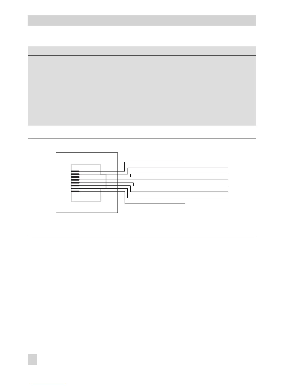
1
2
3
4
5
6
7
8
Device bus
Device bus
+5V
RD
CTS
DTR
TD
GND
Fig. 14 · Assignment of the RJ-45 jack