Parameters
WE Parameter level / Range of values
Max. DHW temperature* 60 °C PA4 / 5 to 90 °C
Hysteresis** 5 °C PA4 / 0 to 30 °C
Charging temperature boost*** 10 °C PA4 / 0 to 50 °C
Max. charging temperature 80 °C PA4 / 20 to 130 °C (only with VF4)
Lag of storage tank charging pump 0.5 PA4 / 0 to 10.0
* Parameters serve as limitation of the adjustment range for the DHW temperature to be set
at the rotary switch
** Deactivation value T =
DHW temperature
+
hysteresis
*** Charging temperature T =
DHW temperature
+
charging temperature boost
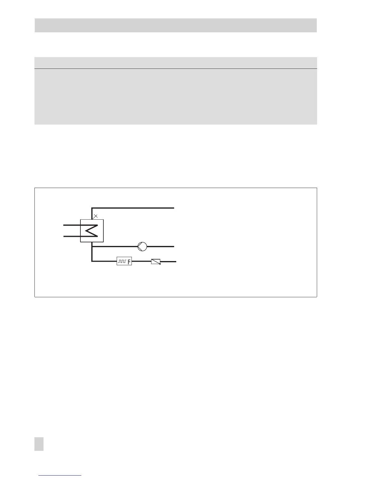
6.3 DHW heating in instantaneous heating system
Without a flowmeter or flow switch, the required
DHW temperature
at sensor VF is only reg-
ulated during the times-of-use of the circulation pump ZP. The flowmeter or flow switch allow
the controller to recognize exactly when DHW is being tapped. By deleting all the
time-of-uses for the circulation pump, it is possible to regulate the required DHW tempera-
ture just while the DHW is being tapping.
With the activated flow sensor V4, the temperature control is moved to upstream of the heat
exchanger: Should the required
DHW temperature
measured at the flow sensor VF4 be too
low, the
Flow temperature set point
upstream of the heat exchanger is raised in steps of
1 °C. When the set point reaches the
Maximum charging temperature
, the temperature is not
raised anymore; an “Err 4” error message is generated.
88 EB 5579 EN
Functions of the DHW circuit
WW
VF
ZP
KW
Fig. 11 · Schematics of an instantaneous heating system with water flowmeter
(CO4 -> F04 - 1, select: AnA)
VF Flow sensor
ZP Circulation pump
WW Hot water
KW Cold water
Water flowmeter