Parameters
WE Parameter level / Range of values
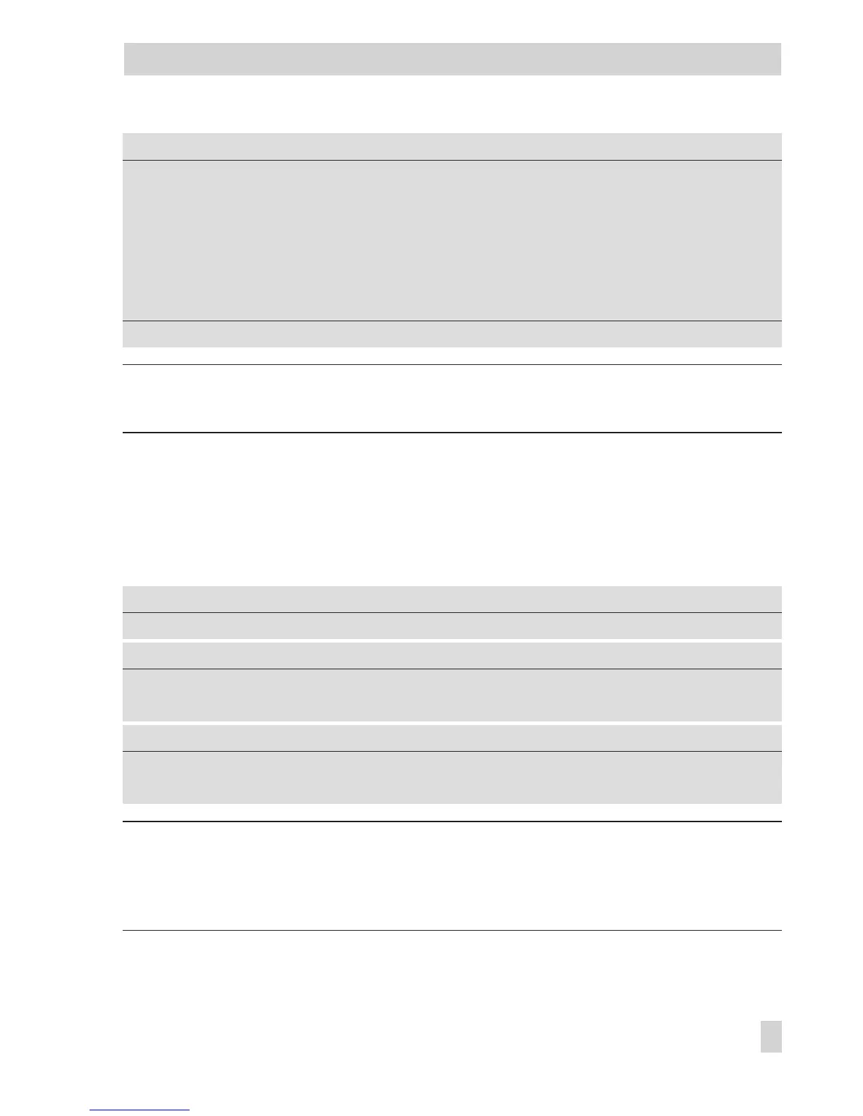
Reduced flow temperature Point 1
Point 2
Point 3
Point 4
60 °C
40 °C
20 °C
20 °C
PA1, 2, 3 / 5 to 130 °C
Return flow temperature Points 1 to 4 65 °C PA1, 2, 3 / 5 to 90 °C
Min. flow temperature 20 °C PA1, 2, 3 / 5 to 130 °C
Max. flow temperature 90 °C* PA1, 2, 3 / 5 to 130 °C
* With CO1, 2, 3 -> F05 - 1, the following applies: Max. flow temperature / 5 to 50 °C (50 °C)
Note: The 4-point characteristic function can only be activated when the Adaptation func-
tion is not active (CO1, 2, 3 -> F08 - 0).
5.2 Fixed set point control
During the times-of-use, the flow temperature can be controlled according to a fixed set
point. Outside the times-of-use, the controller regulates to a reduced flow temperature.
Set the desired rated flow temperature as
Day set point
, and the reduced flow temperature
as
Night set point
.
Functions
WE Configuration
Outdoor sensor AF1 1 CO1 -> F02 - 0
Parameters
WE Rotary switch / Range of values
Day set point 50 °C Top, middle, bottom / Min. to max. flow temperature
Night set point 30 °C Top, middle, bottom / Min. to max. flow temperature
Parameters
WE Parameter level / value range
Min. flow temperature 20 °C PA1, 2, 3 / 5 to 130 °C
Max. flow temperature 90 °C PA1, 2, 3 / 5 to 130 °C
Note: A fixed set point control in heating circuit 2 or 3 with CO2 -> F02 - 0 or
CO3 -> F02 - 0 respectively can only be configured if CO1 -> F02 - 0 is set as well because
the heating circuits 2 and 3 only use the measured outdoor temperature provided by heating
circuit 1.
EB 5579 EN 73
Functions of the heating circuit